LCD Calculator Arduino
Introduction
In this post, we’ll dive into building a simple calculator using Arduino and an LCD display. You’ll learn how to set up the hardware, write the code, and handle user inputs for basic calculations.
Overview
This project demonstrates how to build a basic calculator using an Arduino and a 16x2 LCD display. It supports essential arithmetic operations, including addition, subtraction, multiplication, division, and exponentiation. The calculator takes input via the Serial Monitor, processes the arithmetic operation, and displays the result on the LCD. Additionally, it gracefully handles division by zero and invalid operators, providing appropriate error messages when necessary.
Requirements
Arduino board
LCD display (16x2)
LiquidCrystal library (included by default in Arduino IDE)
10k “A” type Potentiometer
Arduino IDE
How Liquid Crystal Display(LCD) work?
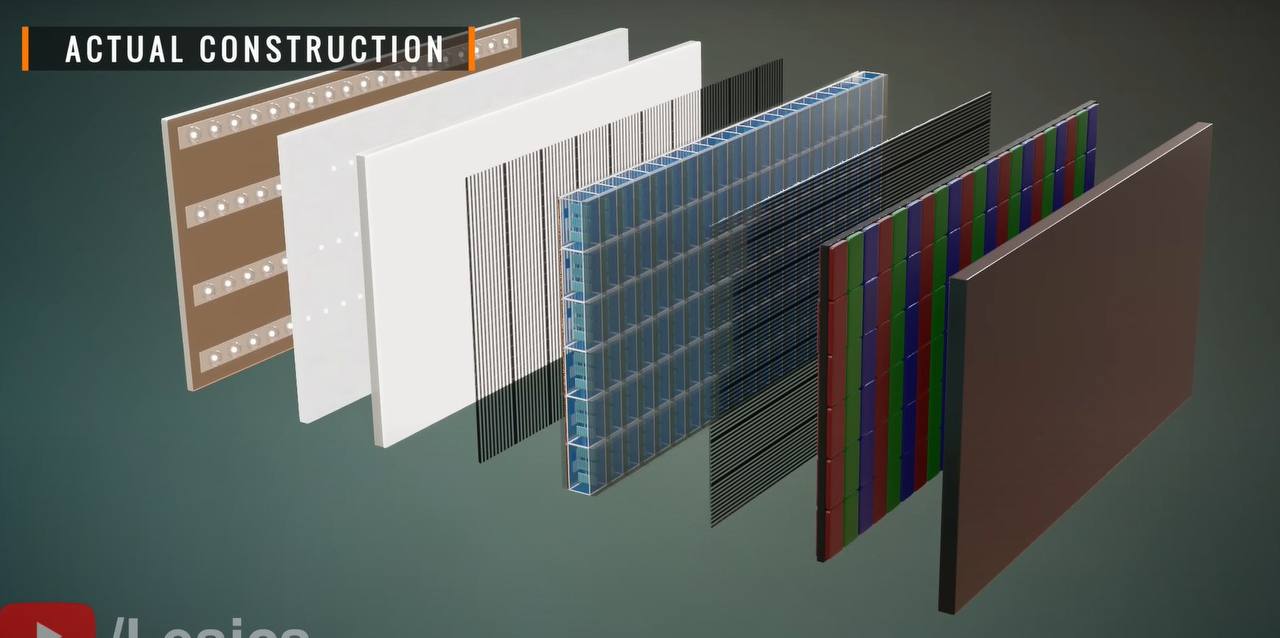
This image shows the internal structure of a usual display screen, with various layers represented. I’ll be explaining the structure of a Liquid Crystal Display layer by layer below via provided image:
Backlight Unit (BLU)
The backlight provides the light source needed to illuminate the display. In an LCD, the backlight is typically located at the back of the display stack. Modern displays often use LEDs arranged along the edges or in an array across the back panel to achieve bright and energy-efficient illumination.
Light Guide Plate (LGP)
This plate guides the light from the backlight across the entire display area. The LGP is usually made of a clear acrylic material with micro-etchings or patterns to distribute light evenly throughout the screen.
Diffuser Layer
Positioned directly above the light guide plate, this layer further spreads the light evenly to prevent any bright or dim spots. The diffuser layer ensures a consistent brightness across the entire viewing area of the display.
First Polarizer
The first polarizer, also known as the horizontal or entrance polarizer, is a transparent film that only allows light waves vibrating in a horizontal orientation to pass through. This polarizing filter helps control the light entering the liquid crystal layer, creating the conditions necessary for the liquid crystals to modulate the light correctly.
Liquid Crystal Layer
The core of the LCD display, this layer consists of liquid crystal molecules sandwiched between two transparent electrodes. When voltage is applied to these electrodes, the liquid crystals align to either allow or block the passage of light. This modulation of light intensity, combined with the color filter layer, forms the images on the screen.
Second Polarizer
This polarizer, sometimes called the vertical or exit polarizer, is aligned perpendicular to the first polarizer. It ensures that only the light manipulated by the liquid crystal layer (in terms of its alignment) passes through, thereby controlling the light and contributing to the image’s clarity and contrast.
Color Filter
Directly above the liquid crystal layer, the color filter is composed of red, green, and blue sub-pixels arranged in a grid. Each pixel on the display has these three sub-pixels, which combine in varying intensities to create the full spectrum of colors needed for the display. The color filter is essential for generating color images, as the liquid crystals themselves only control brightness.
Outer Glass or Protective Layer
This final layer is a transparent glass or plastic sheet that protects the internal components of the display. It shields the delicate layers within while providing a smooth and durable viewing surface.
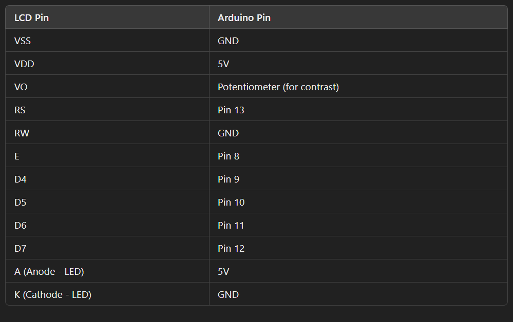
How to Connect LCD to Arduino
Testing
Always start with a simple test code to ensure the LCD is displaying correctly. Arduino’s LiquidCrystal library includes example code for 16x2 displays, which can be helpful for initial testing.
Circuit Schematic
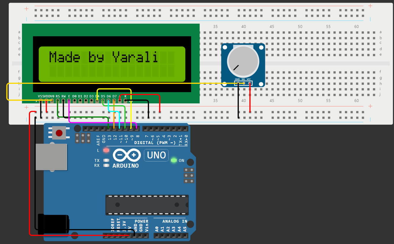
Double-check Connections
Ensure each wire is securely connected to the breadboard and Arduino. Loose connections can cause the LCD to malfunction or display incorrect characters.
Contrast Adjustment
In my circuit diagram, turning the potentiometer clockwise increases contrast, while counterclockwise decreases it. Set the potentiometer to a mid-range position before powering the circuit, then adjust as needed for readability.
Code Implementation
This Arduino program uses an LCD to display simple arithmetic operations. It prompts the user to input two numbers and an operator to perform addition, subtraction, multiplication, division, or exponentiation. Let’s go through the code step-by-step.
1
2
#include <LiquidCrystal.h>
#include <math.h>
The LiquidCrystal.h library manages the communication between the Arduino and the LCD display and math.h is used for advanced mathematical operations (like pow() for exponentiation).
1
2
3
4
5
6
LiquidCrystal lcd(13, 8, 9, 10, 11, 12);
double firstNum = 0;
double secondNum = 0;
char op;
double answer = 0;
String errorMsg = "Math Error";
LiquidCrystal lcd(13, 8, 9, 10, 11, 12): This initializes the LCD object and connects it to the pins of the Arduino. These pins control the LCD’s communication (RS, E, D4, D5, D6, D7).
firstNum, secondNum, op, answer: These variables store the first and second numbers, the operator, and the answer.
errorMsg: This stores a string used to display an error message in case of invalid operations, like division by zero.
1
2
3
4
5
void setup() {
 lcd.begin(16, 2);
 Serial.begin(9600);
 Serial.setTimeout(200);
}
lcd.begin(16, 2): initializes the LCD in a 16x2 (16 columns by 2 rows) configuration.
Serial.begin(9600): starts serial communication at a 9600 baud rate to receive input from the serial monitor.
Serial.setTimeout(200): sets a 200 ms timeout for serial communication to prevent long waits for user input.
1
2
3
4
5
6
7
8
9
10
11
12
13
14
15
// Handling First Input
void loop() {
lcd.setCursor(0, 0);
lcd.print("Enter 1st number");
lcd.setCursor(0, 1);

while(!Serial.available()){
    lcd.blink();
}
lcd.noBlink();

firstNum = Serial.parseFloat();
lcd.print(firstNum);
delay(1000);
lcd.clear();
LCD Prompt: The program prompts the user to enter the first number by positioning the cursor and displaying the message “Enter 1st number.”
Blink Function: While waiting for input (Serial.available()), lcd.blink() makes the LCD cursor blink, visually indicating that the Arduino is waiting for the user’s input. Once input is detected, lcd.noBlink() stops the blinking.
Reading Input: firstNum = Serial.parseFloat(); reads the user’s input as a floating-point number, allowing decimal values.
Displaying and Clearing: The entered number is displayed briefly before clearing the LCD for the next prompt.
1
2
3
4
5
6
7
8
9
10
11
12
13
// Handling Second Input
lcd.print("Enter 2nd number");
lcd.setCursor(0, 1);

while (!Serial.available()) {
    lcd.blink();  // Blink cursor while waiting for input
}
lcd.noBlink();

secondNum = Serial.parseFloat();
lcd.print(secondNum);
delay(1000);
lcd.clear();
This section follows the same steps as for the first number, prompting the user to enter the second number. The blink function is used again to indicate waiting for input.
1
2
3
4
5
6
7
8
9
10
11
12
13
14
// Entering the Operator
lcd.print("Enter operator");
lcd.setCursor(0, 1);

while (!Serial.available()) {
    lcd.blink();  // Blink cursor while waiting for input
}
lcd.noBlink();

op = Serial.read();
Serial.flush();  // Clears the serial buffer after reading
lcd.print(op);
delay(1000);
lcd.clear();
Prompt for Operator: The program prompts the user to enter an arithmetic operator.
Operator Input: op = Serial.read(); reads a single character (the operator) from the serial monitor.
Buffer Flush: Serial.flush(); clears the buffer to prevent any leftover data from affecting the next input.
1
2
3
4
5
6
7
8
9
10
11
12
13
14
15
16
17
18
19
20
21
22
23
//Performing the Calculations
if (op == '+')
    answer = firstNum + secondNum;
else if (op == '-')
    answer = firstNum - secondNum;
else if (op == '*')
    answer = firstNum * secondNum;
else if (op == '/')
    if (secondNum == 0) {
        lcd.clear();
        lcd.print(errorMsg);
        delay(2000);
        return;  // Restart the loop if division by zero occurs
    } else
        answer = firstNum / secondNum;
else if (op == '^')
    answer = pow(firstNum, secondNum);
else {
    lcd.clear();
    lcd.print("Invalid Operator");
    delay(2000);
    return;
}
Operator Check: This block of code uses if statements to determine which operation to perform based on the operator entered by the user.
Division by Zero: If the operator is / and the secondNum is 0, an error message is displayed for 2 seconds, and the program restarts to avoid a crash.
Invalid Operator: If an invalid operator is entered, the program displays an “Invalid Operator” message for 2 seconds before restarting the loop.
1
2
3
4
5
6
7
8
9
lcd.print(firstNum);
lcd.print(op);
lcd.print(secondNum);

lcd.setCursor(0, 1);
lcd.print("Answer = ");
lcd.print(answer);
delay(3000);
lcd.clear();
Format the Display: This section shows the expression (e.g., 5 * 3) on the first line of the LCD and the result (Answer = 15) on the second line.
Delay and Clear: The result remains on the screen for 3 seconds, after which the LCD is cleared, and the program restarts.
Final Overview of Program Flow
The program prompts the user on the LCD to enter the first number, second number, and operator, with a blinking cursor indicating that the system is ready for input. Once the operator is entered, the program performs the calculation according to the selected operator. If the user enters an invalid operator or attempts to divide by zero, an error message is displayed on the LCD. Finally, the LCD shows the full expression along with the result, holding it for 3 seconds before resetting and readying for a new input.
Conclusion
This project demonstrates the construction and functionality of a simple calculator using an Arduino and an LCD display. By integrating the Arduino with a 16x2 LCD screen, we have created a user-friendly interface that guides users through arithmetic operations step-by-step, providing immediate feedback on the display. The project showcases several essential concepts in electronics and programming, including interfacing with serial communication, handling various data types, and implementing error handling for user inputs.
Thank you for following along on this journey to build an Arduino calculator. I hope you found it both informative and inspiring! If you’d like to see this project in action, follow me on Instagram, where I’ll be posting video demos of the calculator in real life, from entering numbers to displaying results on the LCD screen. I’d love to hear your thoughts or see your own versions of this project!
See you in the next project—until then, happy building!