Portable Humidity and Temperature Sensor
Introduction
In our increasingly connected world, monitoring environmental conditions like temperature and humidity has become essential in everything from weather stations to smart home systems. In this tutorial, we’ll walk through creating a temperature and humidity monitoring setup using an Arduino, a DHT11 sensor, and an LCD display. The DHT11 is a popular sensor for these measurements due to its accuracy, affordability, and compatibility with Arduino. By the end of this guide, you’ll have a functioning setup that can display real-time data, helping you get one step closer to understanding and controlling your environment.
Overview
This project is a compact, portable temperature and humidity monitoring system designed for easy use in various environments. Using an Arduino, a DHT11 sensor, and an LCD display, the system provides real-time data on temperature and humidity, allowing users to track environmental conditions wherever they go. The built-in error indication ensures reliability by alerting users if sensor data is unreadable, and the portable design makes it perfect for use in outdoor, mobile, or off-grid applications. This setup is ideal for learners who looking to explore environmental sensing and create their own functional weather station.
Features
Real-time Temperature and Humidity Monitoring
Continuously displays accurate temperature and humidity readings from the DHT11 sensor on a 16x2 LCD screen, updated every few seconds. This display allows users to monitor environmental changes instantly, making it ideal for portable weather stations, greenhouse monitoring, and DIY environmental sensing projects.
Error Indication with Red LED
A built-in red LED signals the user when sensor data is unreadable, such as when the sensor encounters an error or is disconnected. This feature ensures the user is immediately aware of issues, providing a reliable way to identify and troubleshoot potential problems in real-time.
Adjustable LCD Contrast
Includes a 10k potentiometer to adjust the contrast of the 16x2 LCD screen, improving display visibility in various lighting conditions. This feature is especially useful when using the sensor outdoors or in different ambient lighting.
Portable Power Supply
Powered by a 9V battery connected through a breadboard power supply module, making it easy to take the device anywhere without the need for a direct power source. The portable design supports long-term use, ideal for mobile applications or places without stable power access.
Required Components
Arduino Nano (for better portability)
DHT11 Temperature and Humidity Sensor
16x2 LCD Display
Red LED for visual feedback
10k Potentiometer for LCD contrast adjustment
10k Resistor (for DHT11)
330 Ohm Resistor (for LED)
Breadboard and jumper wires
9V Battery with breadboard power supply
Arduino IDE (for coding and uploading to the board)
Download DHT and LiquidCrystal Libraries
How to Download Libraries
You can easily access and install most libraries directly from the Arduino IDE. Simply open the Library Manager by going to Sketch > Include Library > Manage Libraries or use the shortcut Ctrl + Shift + I (Windows) or Cmd + Shift + I (Mac). In the Library Manager, you can search for the library you need, such as DHT(by Adafruit), and then click Install next to it. Libraries which are already built into the IDE, like LiquidCrystal, are ready to use without installation—just include them in your code with:
1
 #include <LiquidCrystal.h>
This makes it quick and simple to add functionality to your projects.
How DHT11 Sensor work?
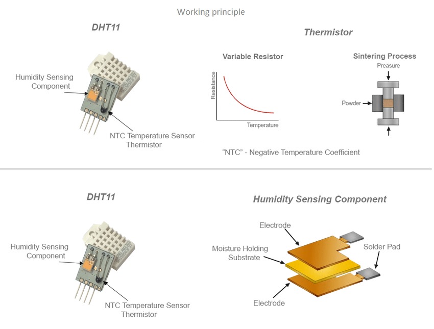
This image shows the internal structure and working principle of the DHT11 sensor, which is used for measuring temperature and humidity. The image provides details on the two main components of the DHT11 sensor: the temperature sensing component and the humidity sensing component.
Temperature Sensing Component
For temperature sensing part, DHT11 uses a thermistor to measure temperature. In a thermistor, electrical resistance changes with temperature due to increased thermal energy affecting the motion of charge carriers (like electrons). At higher temperatures, more charge carriers become available to move, resulting in lower resistance.
Thermistors are usually made of semiconductor materials. In semiconductors, the number of charge carriers increases with temperature as more electrons gain enough energy to jump into the conduction band from the valance band. This causes the thermistor’s resistance to decrease.
They are small, durable and sensitive at low temperature. Thermistors have moderate temperature range (up to 150°C) and low-to-moderate cost (depending on accuracy). DHT11 is a low-cost device and the sensor reading can be up to 2 seconds. It is less accurate compared to more advanced sensors like the DHT22 or others that can measure over a wider temperature range with higher precision. It measures temperature with a Negative Temperature Coefficient (NTC) thermistor in which resistance is negatively correlated with temperature. The graph in the image shows the relationship between temperature and resistance in an NTC thermistor. As the temperature rises, the resistance decreases, allowing the sensor to measure changes in temperature.
Then the DHT sensor’s internal microcontroller reads the change in resistance and converts it into a temperature value using pre-defined calibration data and equations specific to the thermistor’s material properties.
Humidity Sensing Component
The DHT sensor has a capacitive humidity sensor that consists of two electrodes with a moisture-absorbing substrate (usually a polymer) between them. Capacitance is a property that indicates how much electric charge a capacitor can store for a given electric potential. It depends on the area of the plates, the distance between them, and the dielectric constant (a material property related to its ability to store electric energy) of the medium between the plates.
This polymer can absorb water vapor from the surrounding air. When the moisture level in the air (humidity) changes, water molecules (which are polar, meaning they have a partial electric charge) are absorbed by the polymer. Water has a high dielectric constant compared to air, so when it is absorbed into the polymer, the dielectric constant between the capacitor plates increases. The increased dielectric constant causes the capacitance to increase. By measuring this change, the DHT sensor can infer the relative humidity of the surrounding air.
Bonus Information: The Role of Polarity in Water Molecules
Being polar means that the molecule has a partial electric charge on different ends due to the distribution of electrons. Water molecules consist of one oxygen atom and two hydrogen atoms. Oxygen is more electronegative than hydrogen, meaning it pulls electrons toward itself. This creates a negative charge near the oxygen atom and a positive charge near the hydrogen atoms, making the molecule have a dipole — a positive side and a negative side.
This polarity is what allows water to interact strongly with other polar substances and affects the way it behaves in various environments, including its ability to increase the dielectric constant in materials like polymers when absorbed. The increased dielectric constant helps enhance the capacitor’s ability to store electrical charge.
Data Communication Protocol of the DHT11 Sensor
Now that we’ve explored the internal structure of the DHT11, let’s delve into how the sensor communicates with external devices, specifically through its data transmission protocol. After measuring capacitance and resistance, the sensor’s microcontroller (integrated circuit or IC) uses these analog values to calculate temperature and humidity digitally. The DHT11 uses a unique single-wire communication protocol, which allows it to send temperature and humidity data over a single digital pin.
Single-Wire Communication Protocol Explained
The DHT11 sensor communicates using a single-wire protocol, where voltage levels and timing define logic HIGH (1) and logic LOW (0) states. The communication process consists of three main steps: first, the microcontroller sends a request signal to the DHT11. Next, the sensor responds with a response signal. Finally, it transmits 40 bits of data containing temperature and humidity readings.
Images are taken from ElectronicWings.
Request Signal
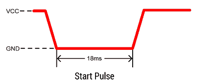
To initiate communication with the DHT11 temperature and humidity sensor, a start signal (or start pulse) needs to be sent from the microcontroller to the DHT11. This signal is essential for synchronizing the sensor with the microcontroller, allowing it to begin sending data.
First, the microcontroller pulls the data line connected to the DHT11 sensor down to a LOW state (0V). This LOW signal should be held for at least 18 milliseconds. This extended LOW signal acts as a prompt that prepares the DHT11 to start the data transfer.
After maintaining the LOW state for at least 18 milliseconds, the microcontroller releases the data line, allowing it to return to a HIGH state (the line automatically returns to a HIGH state). This transition from LOW to HIGH signals to the DHT11 that the request signal is complete.
Response Signal
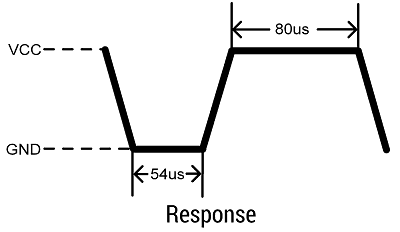
After receiving the request signal from the microcontroller, the DHT11 sensor responds with a confirmation signal called the “response pulse.” This response pulse lets the microcontroller know that the DHT11 has recognized the start(request) pulse and is ready to begin transmitting temperature and humidity data.
Once the DHT11 receives the start pulse, it takes control of the data line by pulling it LOW for approximately 54 microseconds. This initial LOW period is the sensor’s way of acknowledging the start pulse from the microcontroller. After holding the data line LOW for 54 microseconds, the DHT11 then switches the data line to a HIGH state for around 80 microseconds. This HIGH signal completes the response pulse and indicates that the sensor is now ready to transmit its data.
Data Transmission

After sending the response pulse, the DHT11 sensor transmits a data frame containing the temperature, humidity, and a checksum value to ensure data integrity.
Structure of the Data Frame
First Segment (8 bits)
This byte holds the integer part of the humidity value, in percentage (%). The DHT11 measures relative humidity, which indicates the amount of moisture in the air relative to the maximum amount the air can hold at that temperature. For example, if this value is 55, it means the relative humidity is 55%.
Second Segment (8 bits) This byte theoretically would contain the decimal part (or fractional part) of the humidity value. However, it’s important to note that the DHT11 sensor does not measure or provide any fractional humidity values. This means the second byte will always be zero for the DHT11, as it cannot provide humidity with decimal precision.
Third Segment (8 bits)
This byte contains the integer part of the temperature value in Celsius. If this segment holds the value 23, for example, then the temperature is 23°C.
Fourth Segment (8 bits)
Like the humidity fractional part, the DHT11 does not provide a decimal part for temperature, so this segment will also be zero, as it does not measure or provide fractional temperature values.
Heads Up
Some libraries for the DHT11 sensor include software-based interpolation that estimates decimal values to make readings appear smoother. These libraries may add a decimal for temperature to reduce rounding errors or provide slightly more precise results, even if the sensor itself only provides integer values.
Fifth Segment (8 bits)
This is the checksum byte, which is used to verify that the data received is correct. The checksum is calculated by adding together the values in the first four segments (humidity integer, humidity decimal, temperature integer, temperature decimal). The resulting sum is stored in this fifth byte. When the data is received, the microcontroller can add the first four bytes and compare this sum to the checksum byte. If the two values match, the data transmission is considered successful. If they don’t, this indicates an error in the transmission, and the data should not be trusted.
For Instance
Suppose the data frame received from the DHT11 is as follows (in binary):
Humidity Integer: 00110111 (which equals 55 in decimal)
Humidity Decimal: 00000000 (always 0 for the DHT11)
Temperature Integer: 00010110 (which equals 22 in decimal)
Temperature Decimal: 00000000 (always 0 for the DHT11)
Checksum: 01001101 (which equals 77 in decimal)
For verifying the checksum, the microcontroller add four segments’ value in binary and then compare it with the checksum byte. If they match, the data is correct, but if they don’t, there is an error.
End of Data Frame
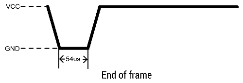
Once the DHT11 sensor has transmitted the data (temperature and humidity values), it enters a low-power consumption mode. During this time, the sensor is idle and does not transmit any further data until the next start pulse is sent by the microcontroller.
Connecting Sensors to Arduino
Wiring LCD
If you’re unsure how to connect LCD display to Arduino, you can check my LCD Calculator Arduino Project for further details.
Wiring DHT11 Sensor
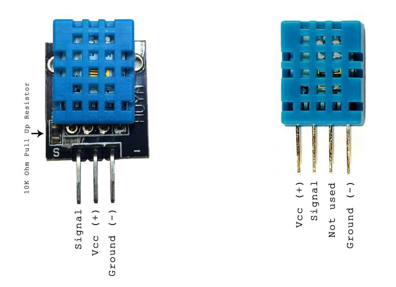
As you can see from the provided image, for a 3-pin DHT11 module, the pins are typically labeled VCC (+), Signal (S), and Ground (-). The 4-pin version has pins labeled VCC (+), Signal, Not used, and Ground (-).
Difference between a DHT11 module and (non-module) DHT11
DHT11 Module
A DHT11 module usually has a small circuit board with a built-in 10k-ohm pull-up resistor connected to the data pin. This resistor stabilizes data communication with the microcontroller (like an Arduino), making it easier to connect directly without extra components.
DHT11 Non-module
The normal version is just the DHT11 sensor component itself, without any additional circuitry. This version does not include a pull-up resistor, so you will need to add one externally (typically a 10k-ohm resistor between the VCC and Signal pins) to ensure stable communication (Check circuit schematic).
Connect the VCC pin of the DHT11 to the 5V pin on the Arduino. This provides the necessary power for the sensor. Then you can connect the Signal pin on the DHT11 to any digital pin on the Arduino. This is where data will be transmitted from the sensor to the Arduino.
Leave the Not used pin on the 4-pin version unconnected. This pin has no function and is not needed for operation.
Last step is connecting the Ground pin of the DHT11 to the GND pin on the Arduino to complete the circuit. After completing these connections, your DHT11 sensor will be ready to communicate with the Arduino.
Circuit Diagram
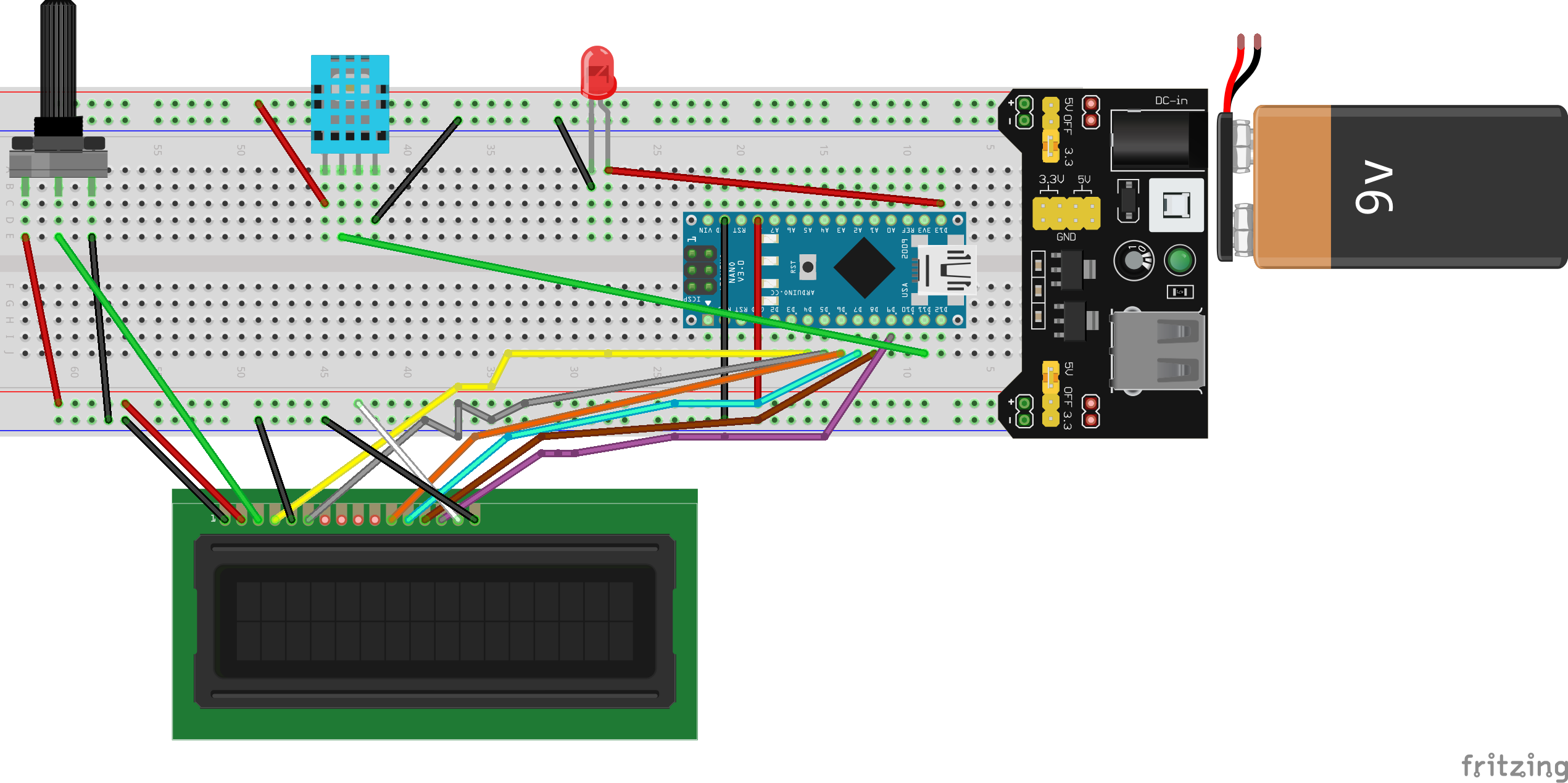
Additional Notes
Place a 10k-ohm resistor between the Signal and VCC pins to ensure stable data transmission for DHT11. Also when working with an LED, don’t forget to place a 330-ohm resistor in series with the LED to limit the current and prevent damaging the LED.
Moreover, in this circuit, a regulated 5V breadboard power supply is used as the primary power source. This type of power supply has built-in voltage regulation, that means it converts input voltage (from a 9V battery in this project) down to a stable 5V output. This regulated 5V output can be connected directly to the Arduino’s 5V pin, bypassing the need for additional voltage regulation on the Arduino itself.
Programming the DHT11 Sensor and LCD
After setting up the hardware and connecting the DHT11 sensor, LCD display, and other components to your Arduino, it’s time to write the code that will bring your project to life. We are lucky that, the DHT.h library simplifies the complex processes involved in communicating with the DHT11 sensor, handling tasks like signal timing and data conversion. This allows us to focus on implementing the main functionality of our project without needing to manage these low-level details manually. Now, let’s get started with the coding process!
1
2
#include <LiquidCrystal.h>
#include <DHT.h>
LiquidCrystal: Manages communication between the Arduino and the LCD display.
DHT: Library for reading data from DHT temperature and humidity sensors.
1
LiquidCrystal lcd(4, 5, 6, 7, 8, 9);
This line creates an lcd object for interfacing with the 16x2 LCD screen. The numbers in parentheses represent the Arduino pins connected to the LCD’s RS, E, D4, D5, D6, and D7 pins, respectively.
1
2
3
#define DHTTYPE DHT11
#define DHTPIN 11
DHT dht(DHTPIN, DHTTYPE);
DHTTYPE: Specifies the sensor model, DHT11 in this case.
DHTPIN: Defines the Arduino pin connected to the DHT11 data pin.
Also, we initialize the DHT object with the DHT pin and sensor type.
1
#define LED_PIN 13
This defines LED_PIN as the pin number for the error indicator LED, which will turn on if the DHT11 sensor reading fails.
1
2
3
4
5
float humidity = 0;
float temperature = 0;
float lastHumidity = 0;
float lastTemperature = 0;
int errorFlag = 0;
humidity and temperature: The current readings from the DHT11 sensor. lastHumidity and lastTemperature: The previous readings, allow us to update the LCD only when there is a change in values. errorFlag: A flag variable used to indicate if there is a sensor error, turning on the LED.
1
2
3
4
5
6
7
8
9
10
11
12
void displayReadings(float temp, float hum) {
   lcd.setCursor(0, 0);
   lcd.print("Temp: ");
   lcd.print(temp);
   lcd.print(" C");
   lcd.print((char)223);

   lcd.setCursor(0, 1);
   lcd.print("Humidity: ");
   lcd.print((int)hum);
   lcd.print("%");
}
displayReadings: Function that displays temperature and humidity values on the LCD screen. lcd.setCursor: Positions the cursor to control where the text appears. -0, 0 represents the first row. -0, 1 represents the second row. lcd.print: Outputs measured values to the LCD. (char)223: Prints the degree symbol (°) next to the temperature(223 is the ASCII value for the degree symbol).
1
2
3
4
5
6
7
8
9
void setup() {
  lcd.begin(16, 2);
  Serial.begin(9600);

  dht.begin();
  delay(500);

  pinMode(LED_PIN, OUTPUT);
}
lcd.begin(16, 2): Initializes the 16x2 LCD display. Serial.begin(9600): Starts serial communication for debugging or monitoring values. dht.begin(): Initializes the DHT11 sensor. delay(500): Adds a brief delay to stabilize the sensor at startup. pinMode(LED_PIN, OUTPUT): Configures the LED pin as an output.
1
2
3
void loop() {
  humidity = dht.readHumidity();
  temperature = dht.readTemperature();
humidity and temperature: Capture current sensor readings for humidity and temperature.
To display temperature in Fahrenheit, add “true” argument inside the read function (dht.readTemperature(true)).
1
2
3
4
5
6
7
8
9
10
  if (isnan(humidity) || isnan(temperature)) {
    if (errorFlag == 0) {
      lcd.clear();
      lcd.print("Failed to Read!");

      digitalWrite(LED_PIN, HIGH);
      errorFlag = 1;
    }
    return;
  }
isnan: Checks if the readings are “Not a Number”(NaN), which indicates a sensor error. When the DHT sensor fails to provide a valid temperature or humidity reading, the dht.readHumidity() or dht.readTemperature() functions will return NaN.
If the sensor fails, lcd.clear clears the LCD, displaying “Failed to Read!”. digitalWrite(LED_PIN, HIGH): Turns on the LED to indicate the error. errorFlag = 1: Sets the error flag to 1, avoiding repeated attempts to read when an error is detected.
1
2
3
4
5
6
  if (errorFlag) {
    lcd.clear();
    digitalWrite(LED_PIN, LOW);
    displayReadings(temperature, humidity);
    errorFlag = 0;
  }
If the sensor starts working after an error, this code clears the error message, turns off the LED, and resets errorFlag to 0.
1
2
3
4
5
6
  if ((temperature != lastTemperature) || (humidity != lastHumidity)) {
    displayReadings(temperature, humidity);
  }
  lastTemperature = temperature;
  lastHumidity = humidity;
}
temperature != lastTemperature and humidity != lastHumidity: Checks if there’s any change in the readings. displayReadings: Updates the display only if there’s a change. lastTemperature and lastHumidity: Update the last recorded values for comparison in the next loop.
Conclusion
Thank you all for following along on this journey to build a portable temperature and humidity monitor with Arduino. I hope you found the project inspirational and helpful! If you’d like to see this project in action, follow me on Instagram, where I’ll be posting video demos of the device in use, from reading sensor data to displaying it on the LCD screen. I’d love to hear your feedback and see your versions of this project!
See you in the next build——until then, happy coding and creating!