Portable Distance Sensor
Introduction
As technology continues to evolve and shape our daily lives, tools that enhance convenience and precision are more important than ever. In this tutorial, we’ll explore how to create a portable distance detector using an Arduino, an HC-SR04 ultrasonic sensor, and an LCD display. The HC-SR04 is widely known for its ability to measure distances accurately and efficiently by emitting ultrasonic waves and calculating the time it takes for the echo to return.
Overview
What sets this project apart is its practicality: by simply pressing a button, the device calculates and displays the distance between the sensor and an object in real-time. Along the way, we’ll also cover essential concepts like software debouncing to ensure accurate button presses and a moving average filter to smooth out distance readings for reliable results. Additionally, it includes an error indication system to alert you when the sensor fails to detect a valid distance, ensuring reliability in various scenarios. By the end of this guide, you’ll have a handy tool that demonstrates the power of Arduino for real-world applications.
Features
Real-Time Distance Measurement
Accurately measures the distance between the sensor and an object using ultrasonic waves and displays the measured distance instantly on the LCD screen.
Button-Activated Operation
The device operates at the press of a button, triggering the measurement and display of the distance, providing a simple and user-friendly interface.
Software Debouncing
To eliminate false triggers from button presses, software debouncing ensures that only valid button actions are detected, enhancing the system’s reliability.
Moving Average Filter
The distance readings are smoothed using a moving average filter, which helps reduce fluctuations and noise, providing more accurate and stable measurements.
Error Indication
The project includes an error indication system that alerts users when the sensor fails to provide a valid distance reading, ensuring reliable performance.
LCD Display
A clear and easy-to-read LCD display shows the calculated distance in real-time, making it simple to monitor measurements.
Compact and Portable
The system is designed to be compact and easily portable, allowing it to be used in a variety of environments.
Required Components
Arduino Nano (for better portability)
HC-SR04 Ultrasonic Distance Sensor
10k Ohm Resistor (Between Echo and Ground pin)
16x2 LCD Display
10k Potentiometer for LCD contrast adjustment
Red LED for feedback
330 Ohm Resistor (for LED)
Push Button
10k Ohm Resistor (for Pull-Up)
Breadboard and Jumper Wires
External Power Supply
Arduino IDE (for coding and uploading to the board)
Download LiquidCrystal Libraries
How to Download Libraries
If you’re not familiar with downloading and installing libraries in the Arduino IDE, you can check out my Portable Humidity and Temperature Sensor for a comprehensive explanation. Additionally, before getting started, unlike the temperature and humidity sensor, which we controlled using the DHT11 library in our previous project, we will control the HC-SR04 sensor manually, without using any external libraries.
What is HC-SR04 ultrasonic sensor and how it works?
The HC-SR04 ultrasonic sensor is a simple and effective device for measuring distances using sound waves.
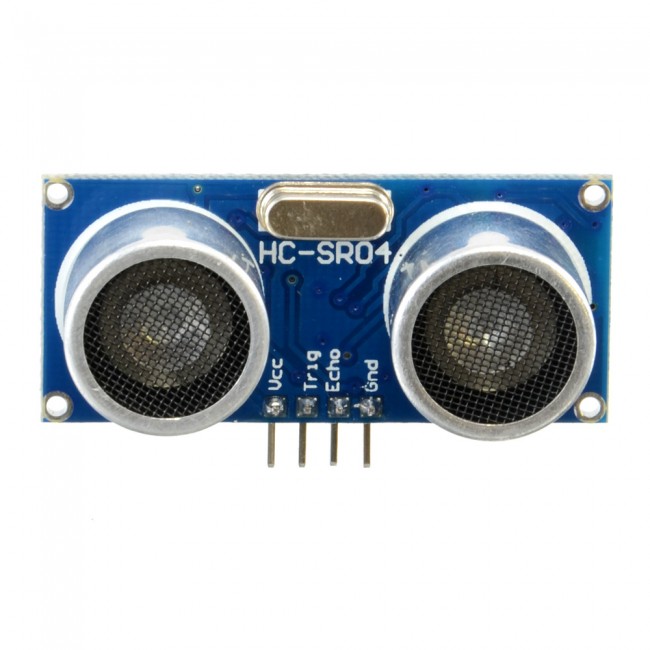
VCC: This pin supplies power to the sensor. It typically requires a 5V power source.
Trig (Trigger): This pin is used to initiate the transmission of ultrasonic waves. A microcontroller sends a short pulse (usually 10 microseconds) to this pin to trigger the sensor to emit an ultrasonic burst.
Echo: This pin outputs a signal back to the microcontroller. The duration of this signal corresponds to the time taken for the ultrasonic wave to travel to the object and back. The microcontroller can then calculate the distance based on this duration.
GND: This pin is connected to the ground of the power supply to complete the circuit.
How Ultrasonic sensor works?
Triggering Ultrasonic Waves
The trigger pin is supplied with a 10 µs high pulse to activate the sensor. This causes the transmitter to emit 8 ultrasonic bursts at a frequency of 40 kHz (beyond human hearing range).
Propagation and Reflection
These sound waves travel through the air. When they hit an obstacle, they reflect back toward the sensor.
Echo Reception
The receiver detects the reflected sound waves. The sensor measures the time taken between sending the ultrasonic burst and receiving the echo.
Overall, the HC-SR04 ultrasonic sensor provides a non-contact method for measuring distances using ultrasonic waves, making it versatile for various applications requiring distance sensing.
Images are taken from element14 presents.
Now, let’s learn about the Physics principles behind it.
What is Ultrasonic Sound?
Sound is a vibration that travels through a medium like air or water, and its frequency determines how we perceive it. Human ears can detect sounds in the range of 20 Hz to 20,000 Hz, which is known as the audible range.
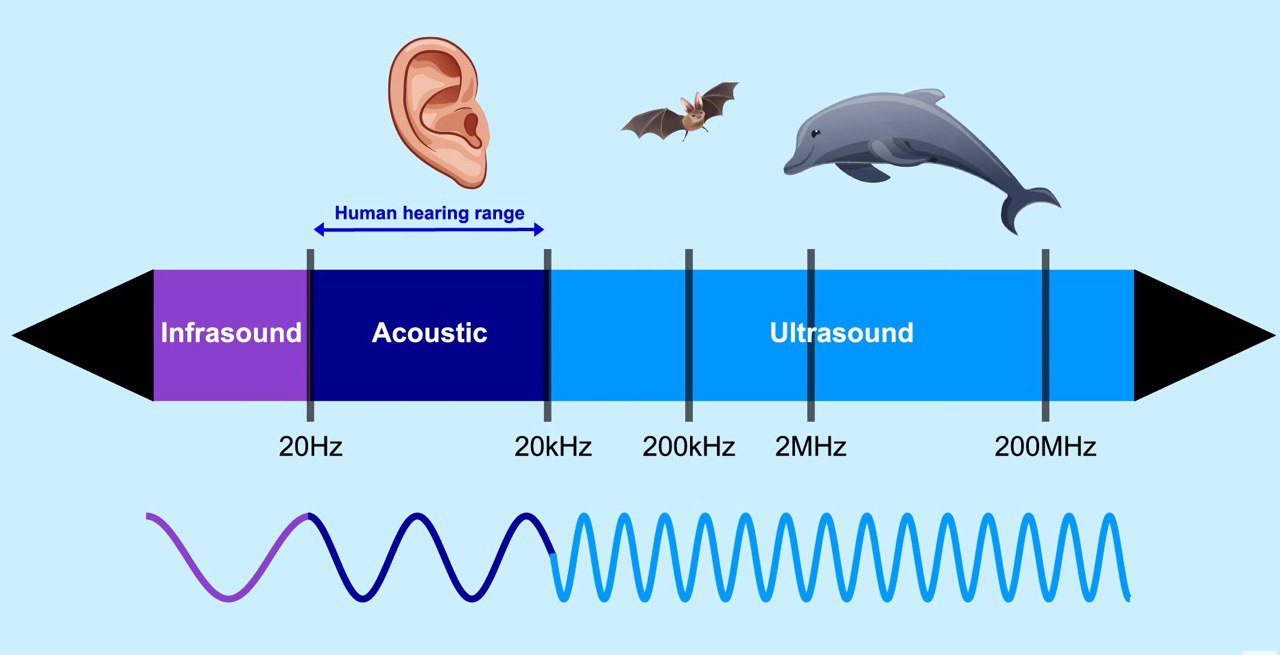
Ultrasonic sound refers to sound waves with frequencies above 20,000 Hz—too high for human hearing. Despite being inaudible to us, these high-frequency sound waves are extremely useful in various applications. The unique properties of ultrasonic sound, such as its ability to reflect off objects and maintain its directionality, make it ideal for measuring distances, detecting objects, and even medical imaging (like ultrasounds).
What is the Piezoelectric Effect?
The piezoelectric effect is the property of certain materials (quartz, ceramics like PZT(lead zirconate titanate)) to generate an electric signal in response to applied mechanical stress. The reverse is also true: applying an electric field to these materials causes them to deform or vibrate mechanically.
Direct Piezoelectric Effect
When you apply pressure or strain to a piezoelectric material, its internal structure generates an electrical charge. This property is useful for creating sensors that convert mechanical energy (like vibrations) into electrical signals.
Reverse Piezoelectric Effect
When you apply an electrical voltage to a piezoelectric material, it changes shape or vibrates. This is useful for creating actuators or devices that produce sound waves, such as ultrasonic transmitters.
What is a transducer?
A transducer is a device that converts one form of energy into another. It is commonly used in measurement, sensing, and control systems. Transducers play a critical role in many engineering and scientific applications, as they bridge the gap between physical phenomena and electronic signals that can be measured or controlled. In the context of the HC-SR04 ultrasonic sensor, it is basically a piezoelectric transducer, the device that uses the piezoelectric effect to convert between mechanical energy (such as vibrations or pressure) and electrical energy.
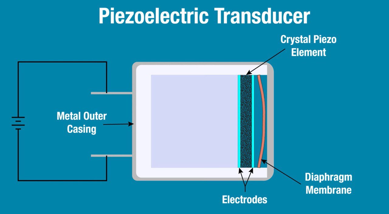
The provided image shows a diagram of a piezoelectric transducer, which is a device that converts electrical energy into mechanical vibrations (sound) or vice versa, using the piezoelectric effect.
Components
Metal Outer Casing
The metal outer casing provides structural support and protection for the internal components of the transducer. It also helps to shield the piezoelectric element from external mechanical impacts and electrical noise.
Crystal Piezo Element
The core of the transducer, this piezoelectric crystal, generates mechanical vibrations when an electrical voltage is applied (or generates an electrical signal when it experiences mechanical stress). Common materials used include quartz, lead zirconate titanate (PZT), and other ceramics.
Piezoelectric Effect
This is the property of certain materials to generate an electric charge in response to applied mechanical stress. Conversely, they can deform (change shape) when an electric field is applied.
Electrodes
These are conductive layers placed on either side of the piezoelectric element to apply an electrical voltage across it or to collect the electrical charge generated by it. The electrodes enable the piezoelectric effect to be utilized in a controlled manner. Electrodes are typically made of thin metal films and are in direct contact with the piezoelectric element to ensure efficient transfer of electrical energy.
Diaphragm Membrane
The diaphragm membrane is a flexible component that vibrates in response to the mechanical movement generated by the piezoelectric element. This vibration is what produces sound waves in ultrasonic transducers or captures sound waves in microphones. The diaphragm is crucial in converting the mechanical vibrations of the piezoelectric element into sound waves (or vice versa). It needs to have the right balance of flexibility and strength to effectively transmit these vibrations.
Working Principle
Transmission Mode (Generating Sound)
Electrical to Mechanical: When an alternating voltage is applied across the electrodes, the piezoelectric element deforms and vibrates. These vibrations are transmitted to the diaphragm, which in turn generates sound waves (ultrasonic waves) that propagate through the medium (air, water, etc.).
Reception Mode (Detecting Sound)
Mechanical to Electrical: When sound waves hit the diaphragm, they cause it to vibrate. These vibrations are transferred to the piezoelectric element, which deforms and generates an electrical signal across the electrodes. This signal can then be processed and measured.
Propagation of the Sound
Beam Shape
Ultrasonic sensors typically produce a conical beam of sound, which spreads out as it moves away from the sensor. The width of the beam depends on the size and design of the sensor. For example, a sensor with a narrow beam will focus the ultrasonic waves more tightly, whereas a wider beam will cover a larger area.
Beam Angle
The beam has an angle of spread (often referred to as the “beam angle”), which determines the sensor’s effective coverage area. The angle can vary depending on the sensor design, but it generally ranges from 15 to 30 degrees for many common ultrasonic sensors like the HC-SR04.
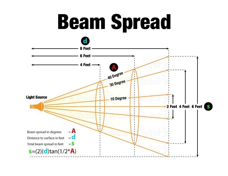
Emitting Ultrasonic Waves
The ultrasonic sensor sends out sound waves in the form of high-frequency vibrations through a piezoelectric transducer. These waves travel outward in the shape of a cone, spreading as they move away from the sensor. When these sound waves hit an object, part of the waves are reflected (echo) back toward the sensor.
Factors Affecting Beam Propagation
Environment: The medium through which the waves propagate (e.g., air, water, or another substance) can affect the behavior of the sound waves. For example, temperature, humidity, and air pressure can influence the speed of sound and thus the accuracy of the distance measurement. Higher temperatures increase the speed of sound, slightly affecting the measurement.
Obstacles and Surface Texture: The angle at which the sound waves hit an object, as well as the surface texture, can affect how much sound is reflected back. Smooth, flat surfaces reflect sound waves more effectively than irregular or absorbent surfaces.
Beam Spread: As the ultrasonic beam propagates, it becomes wider and weaker. This means the sensor may lose accuracy at longer distances, especially if the object being measured is outside the optimal beam width.
Distance Range of HC-SR04
Minimum Distance: 2 cm
This is the shortest distance the sensor can reliably detect. Objects closer than this may not reflect the signal properly.
Maximum Distance: 400 cm (4 meters)
This is the farthest distance the sensor can measure. Beyond this, the echo may be too weak or may take too long to return for reliable detection.
Accuracy
The HC-SR04 offers an accuracy of approximately ±3 mm.
This means the measured distance can be off by up to 3 mm, which is sufficient for most applications like robotics, obstacle avoidance, and basic distance measurement.
Practical Impact of Beam Propagation
At short distances, the ultrasonic beam is more focused, and the sensor will give precise readings. As the distance increases, the beam spreads out, meaning it may encounter more objects, causing potential interference or less accurate measurements. The sensor’s beam angle also limits its ability to detect objects outside its line of sight or if the object is very small relative to the beam size.
Bonus Information: Why Ultrasonic sensors cannot work in Vacuum?
Medium Requirement
Ultrasonic sensors rely on the propagation of sound waves, which need a medium to travel through (such as air, liquid, or solid). In a vacuum, there is no medium (like air) to carry the sound waves. As a result, the sound waves cannot propagate.
Absence of Molecules
In a vacuum, there are no molecules to vibrate and transmit the sound waves. Sound is essentially a mechanical wave that travels by vibrating molecules. Without molecules, sound waves cannot travel, rendering ultrasonic sensors ineffective.
Comparison to Other Sensors
Infrared Sensors: Unlike ultrasonic sensors, infrared sensors can work in a vacuum because they rely on the emission and detection of infrared light, which does not require a medium to travel through.
Laser Rangefinders: These also work in a vacuum because they use light (typically lasers) to measure distance, which can propagate through a vacuum.
Connecting Sensors to Arduino
Wiring LCD
If you’re unsure how to connect LCD display to Arduino, you can check my LCD Calculator Arduino Project for further details.
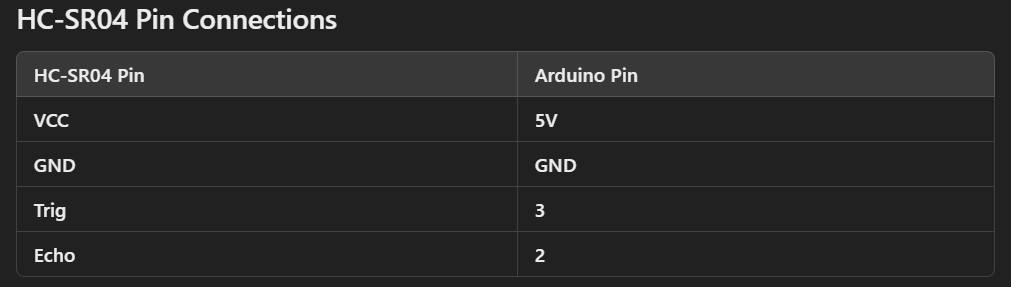
Wiring HC-SR04
As l mentioned earlier, the HC-SR04 ultrasonic distance sensor has four pins, each serving a specific function.
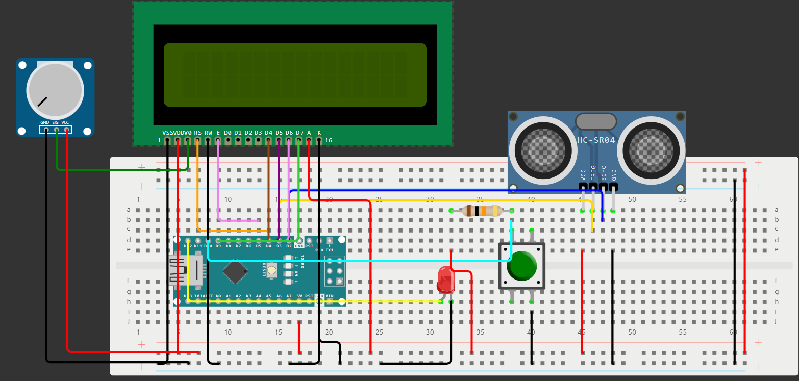
Circuit Diagram
Additional Notes
The Echo pin generates a pulse whose voltage can sometimes be inconsistent or potentially spike. A pull-down resistor (like 10k ohm) helps ensure the voltage level on the Echo pin stays at 0V (LOW) when no signal is present, protecting the Arduino from stray signals. Also when working with an LED, don’t forget to place a 330-ohm resistor in series with the LED to limit the current and prevent damaging the LED.
Common Ground
Regardless of whether you’re using an external or internal power supply, the ground pin of the ultrasonic sensor must be connected to the ground of your main circuit (which is usually the ground of the Arduino or microcontroller). This is critical because both the Arduino and the ultrasonic sensor need to have a common reference point for the signals to work correctly. Without connecting the grounds, the sensor and the microcontroller won’t share the same reference, causing unreliable readings or communication issues.
Programming the HC-SR04 Sensor and LCD
After assembling the hardware and connecting the HC-SR04 ultrasonic sensor, LCD display, push button, and LED to your Arduino, it’s time to program the system to measure distances and provide real-time feedback. The HC-SR04 ultrasonic sensor is a versatile component that emits ultrasonic waves to measure distances by calculating the time it takes for the echo to return. However, raw sensor data can be noisy and inconsistent. To address this, the program integrates a moving average filter to stabilize the readings, ensuring more accurate and reliable results. Additionally, the program is designed with user interaction in mind. A push button triggers the measurement process, with button debouncing effectively implemented to avoid false triggers caused by mechanical bounce, while a status LED and an LCD display provide feedback to the user. The code also includes error detection and handling for situations where no echo is received, lighting up the LED and displaying an error message on the screen.
What is Software Filtering?
Software filtering refers to the process of manipulating and refining data through software algorithms to remove noise, improve quality, or extract meaningful information. This technique is widely used in various applications, such as signal processing, image enhancement, data analysis, and communication systems.
Purpose
Reduce noise or unwanted components from raw data.
Smooth fluctuations or spikes in data.
Extract specific features or patterns.
Enhance data for better interpretation or decision-making.
Common Types of Filters
Low-pass Filter: Removes high-frequency noise while preserving slower-changing signals.
High-pass Filter: Removes low-frequency trends or drifts.
Band-pass Filter: Allows only a specific range of frequencies to pass through.
Median Filter: Replaces a data point with the median of its neighboring points to reduce noise while preserving edges in signals or images.
Kalman Filter: An advanced filter for predicting and correcting dynamic systems with noise.
Moving Average: Smoothens data by averaging a fixed number of data points.
Applications
Signal Processing: Reducing noise in audio signals or sensor data.
Image Processing: Enhancing image quality by removing artifacts.
Control Systems: Smoothing input signals for better system stability.
Scientific Data: Cleaning experimental data for analysis.
IoT Devices: Filtering noisy data from sensors like DHT11.
Implementation: Software filters are implemented using mathematical algorithms and are coded in programming languages like C, Python, or MATLAB. They are typically integrated into firmware, applications, or data processing pipelines.
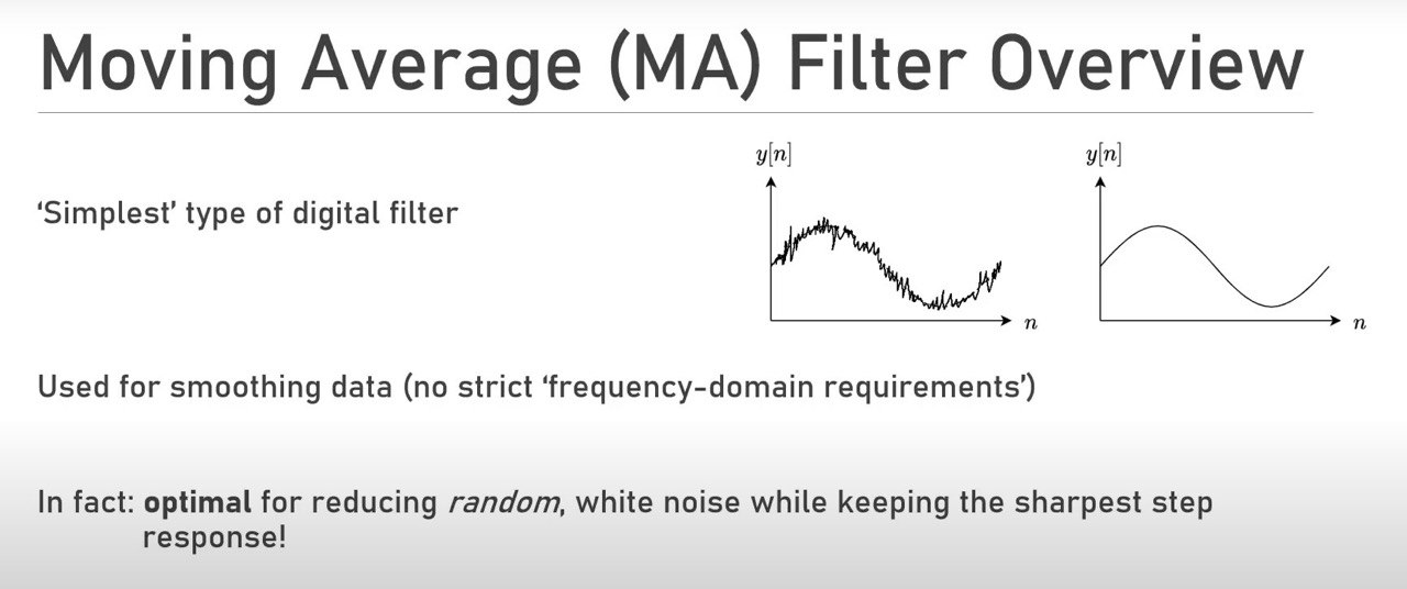
What is Moving Average Filter?
A moving average filter is a simple, yet effective, filtering technique used to smooth data by reducing noise and fluctuations. It achieves this by averaging a fixed number of recent data points (a “window”) and replacing the current data point with this average. For this project, l will be using MVA.
Types
Simple Moving Average (SMA)
All data points in the window are equally weighted.
Weighted Moving Average (WMA)
Recent data points are assigned higher weights, improving response to trends.
How It Works
Window Selection
Choose the size of the “window” (e.g., 3, 5, or 10 data points). A larger window provides smoother results but may lag or miss rapid changes in the data.
Averaging At each step, the filter calculates the average of the current data point and its surrounding neighbors within the window.
Sliding Window
The window “slides” as new data points are processed, ensuring the filter remains updated.
Benefits
Smoothens jittery distance measurements.
By averaging multiple readings, the algorithm minimizes the effect of noise or spikes in individual measurements. Provides a more reliable reading for further processing, like triggering alarms or controlling actuators.
Sudden changes in the distance readings are dampened, making the output more stable and reliable.
Disadvantages
Can lag behind rapid changes in the signal (especially with larger windows).
May reduce the sharpness of important signal features.
Button Debouncing
The Arduino operates at a clock speed of 16 MHz, meaning it can execute up to 16 million instructions per second. Due to this high speed, it can read the state of a button thousands of times while you press it.
Bouncing in pushbuttons refers to the mechanical phenomenon where, when a button is pressed or released, the contacts inside the switch don’t immediately settle into their final open or closed state. Instead, they rapidly open and close several times within a few milliseconds before stabilizing. This happens because the metal contacts physically “bounce” due to mechanical vibrations and imperfections when they come together or separate. In electronics, this bouncing effect can cause multiple signals to be registered by a microcontroller, even though the user intended to press the button only once. To handle this, a technique called debouncing is often used. Debouncing can be done in two ways:
Software Debouncing
Adding a small delay (e.g., 10-50 ms) in the code after detecting a button press to ignore any further changes in the button state during this period. This way, only the final, stable state is registered.
Hardware Debouncing
Using components like resistors, capacitors, or specialized circuits to smooth out the signal and filter out the bounces.
Unpredictable Results Because the Arduino reads the button state so frequently, it might catch the button in the middle of bouncing, leading to unpredictable results. This results in the program sometimes showing the correct behavior (on or off) and other times not, depending on the exact moment it reads the button state.
Correct Behavior Occasionally Just like a broken clock is correct twice a day, the program might occasionally catch the button in a stable state, displaying the correct behavior. However, much of the time, the readings will be inconsistent due to the high reading frequency and bouncing effect.
Now, let’s get started.
1
2
3
4
5
6
7
8
9
10
11
12
13
14
15
16
17
18
19
20
21
#include <LiquidCrystal.h>
#define trigP 3
#define echoP 2
#define NUM_READINGS 50
#define ledP 12
#define buttonP 10
#define interval 10000
float lastDistance = 0;
int errorFlag = 0;
float total = 0;
unsigned long previousMillis = 0;
int buttonVal = 1;
int oldVal = 1;

int actionState = 0;
float newReading = 0;
LiquidCrystal lcd(4, 5, 6, 7, 8, 9);


float distanceToTarget = 0;
float readings[NUM_READINGS] = { 0 };
LiquidCrystal lcd(4, 5, 6, 7, 8, 9): Initializes the LCD with its control pins connected to Arduino pins 4, 5, 6, 7, 8, and 9.
Pin Definitions
trigP (pin 3): Trigger pin for the HC-SR04.
echoP (pin 2): Echo pin for the HC-SR04.
ledP (pin 12): Error indicator LED.
buttonP (pin 10): Push button for user interaction.
Constants
NUM_READINGS: Size of the moving average filter buffer (50 readings).
interval: Maximum measurement interval (10 seconds).
State Variables
actionState: Indicates if the system is in measurement mode.
errorFlag: Tracks if there’s an error (e.g., no echo detected).
total: Sum of the last 50 readings for moving average.
distanceToTarget: Filtered distance (moving average).
readings[NUM_READINGS]: Buffer for storing distance readings.
lastDisplayedDistance: Tracks the last displayed distance to avoid redundant updates.
previousMillis: Tracks the last measurement time for timing control.
1
2
3
4
5
6
7
8
9
void setup() {
  Serial.begin(9600);
  pinMode(ledP, OUTPUT);
  pinMode(trigP, OUTPUT);
  pinMode(echoP, INPUT);
  pinMode(buttonP, INPUT_PULLUP);
  lcd.begin(16, 2);
  delay(20);
}
Serial communication is started at 9600 baud for debugging.
Pin modes are set:
OUTPUT for trigP (to send ultrasonic pulses) and ledP (to indicate error).
INPUT for echoP (to receive ultrasonic signals) and buttonP (to detect user input).
The LCD is initialized with dimensions 16x2.
A short delay ensures all hardware is stable.
1
2
3
4
5
6
7
8
9
10
11
12
13
14
15
16
17
18
19
20
21
22
23
24
void promptUser() {
  static unsigned long lastDebounceTime = 0;
  const unsigned long debounceDelay = 50;
  if (!actionState) {
    while (true) {
      lcd.setCursor(0, 0);
      lcd.print("Click button for");
      lcd.setCursor(0, 1);
      lcd.print("measurement");

      buttonVal = digitalRead(buttonP);  // Read the button state

           if (buttonVal != oldVal)
        lastDebounceTime = millis(); // Reset the debounce timer

          if ((millis() - lastDebounceTime) > debounceDelay && buttonVal == LOW) {
          actionState = 1;
          break;
      }
       oldVal = buttonVal;
    }
    lcd.clear();
  }
}
Purpose: Waits for the user to press the button before entering measurement mode.
Displays a message: “Click button for measurement” on the LCD.
Implements debounce logic to prevent multiple detections from a single button press: Checks if the button state changes and ensures the change persists for at least 50ms. When the button is pressed (LOW state), sets actionState to 1, signaling that the system should take a measurement.
If the current button state is different from the previous button state, the debounce timer (lastDebounceTime) is reset. This ensures we start measuring the debounce delay from the moment the state changes.
This method assumes that the duration of a human button press is significantly longer than the debounce delay.
Explanation of Assumptions
Human Reaction Time
A typical human button press lasts anywhere from 100 milliseconds to 500 milliseconds or longer. The debounce delay is usually set to a small value, like 25-50 milliseconds.
Mechanical Bounce
When a button is pressed, mechanical vibrations cause the signal to fluctuate (bounce) rapidly between HIGH and LOW for a brief period, usually 5 to 20 milliseconds.
Filtering Out Bounces
By setting the debounce delay to 50 milliseconds, the code effectively ignores these rapid bounces.
If the button state remains stable for more than 50 milliseconds, the code considers it a valid press.
Valid Press Duration
Since human button presses typically last much longer than 25 milliseconds, the debounce delay allows the system to reliably detect valid presses and ignore false bounces.
Example Timeline
Button Pressed
At t = 0 ms: The button is pressed (HIGH → LOW).
Between t = 0 ms and t = 15 ms: Bounces occur (LOW, HIGH, LOW, etc.).
Debounce Delay
At t = 25 ms: The button state has remained LOW for 25 ms, confirming a valid press.
The code registers the button press and sets actionState = 1.
Button Held
If the button continues to be held for 100 ms or more, the debounce mechanism works without issue.
pulseIn Function
The pulseIn() function in Arduino is used to measure the duration of a high or low pulse on a pin. It’s a very useful function for reading signals from devices like ultrasonic sensors or infrared receivers.
1
pulseIn(pin, value, timeout)
Parameters
pin: The pin number to read the pulse from.
value: Either HIGH or LOW, indicating whether to measure the duration of a high pulse or a low pulse.
timeout (optional): The maximum time (in microseconds) to wait for a pulse to start or stop. The default is 1 second.
Returns The duration of the pulse (in microseconds).
Returns 0 if no pulse starts before the timeout.
Pin configuration: The pin must be set to INPUT mode for pulseIn() to work correctly.
Interrupts: While pulseIn() is running, interrupts are disabled. Be cautious when using it in time-sensitive applications.
Accuracy: It’s generally accurate for pulses ranging from a few microseconds to a few seconds. However, for very short pulses, results might be less accurate.
Timeout: Use the timeout parameter to avoid blocking the code if no pulse is detected.
1
2
3
4
5
6
7
8
9
10
11
12
13
14
15
16
17
18
float getDistance() {
  long duration = 0;
  const float velocity = 0.0343;
  digitalWrite(trigP, LOW);
  delayMicroseconds(2);
  digitalWrite(trigP, HIGH);
  delayMicroseconds(10);
  digitalWrite(trigP, LOW);
  duration = pulseIn(echoP, HIGH, 30000);
  delay(20);


  if (duration == 0) {
    return -1;
  } else

    return (velocity * duration / 2.);
}
Sends a 10-microsecond pulse on the trigP pin. Waits for the echo and measures its duration using pulseIn(). Converts the duration to distance using the speed of sound (velocity = 0.0343 cm/μs). Returns the calculated distance. If no echo is detected, returns -1 (error state).
Delay Between Measurements
Sometimes, inadequate delay between measurements can cause issues with pulseIn() because it might not have enough time to register the pulse properly. Adding a small delay (in the range of a few milliseconds) can sometimes stabilize the readings. Additionally, you may think that adding a delay() after the pulseIn() function interrupts the program incorrectly. However, it’s important to understand how both functions work:
pulseIn(): This function waits for a pulse to start and measures its duration. During this time, the program is blocked, meaning it does not execute any other code until the pulse measurement is complete or it times out.
delay(): This function pauses the program for the specified amount of time (in milliseconds). Like pulseIn(), it also blocks the program, meaning nothing else can run during the delay.
Minimize pulseIn Timeout
The HC-SR04 maximum measurable range is about 400 cm. At a speed of sound of 0.0343 cm/μs, the echo should return within 23 ms (round trip).
Set the timeout to slightly above this, say 30 ms, to handle maximum distances.
If you don’t need to measure far distances, reduce the timeout further for a redundant timeout.
1
2
3
4
5
6
7
8
9
10
11
12
13
float lastDisplayedDistance = -1;

void displayDistance(float distance) {
  if (abs(distance - lastDisplayedDistance) > 0.1) { // Update only if there's a significant change
  lcd.print("Distance:");
    lcd.setCursor(9, 0); // Position where the distance value is displayed
    lcd.print("     "); // Clear the old value (only the number area)
    lcd.setCursor(9, 0);
    lcd.print(distance, 1); // Print the new value with 1 decimal place
    lcd.print(" cm ");
    lastDisplayedDistance = distance; // Update the stored value
  }
}
Displays the distance on the LCD:
Checks if the new distance differs significantly from the last displayed value (reduces redundant updates).
Clears the old distance value and updates the display with the new distance, formatted to one decimal place.
Why Strings Do Not Flicker
“Distance:” Is Static:
The string “Distance:” is always written in the same position at the beginning of the line (lcd.setCursor(0, 0)).
Since it is not being cleared or rewritten repeatedly in the displayDistance() function, it appears stable.
Partial Clearing
When updating the distance value, we only clear the numeric part (lcd.print(“ “)), which ensures that static strings like “Distance:” remain untouched.
Efficient Updates
We update the numeric value (distance) only when there is a significant change (abs(distance - lastDisplayedDistance) > 0.1). This prevents unnecessary screen updates and keeps the display stable.
Consistent Formatting
The distance value is always written in the same position (lcd.setCursor(9, 0)), followed by “ cm”. This consistency ensures that only the numeric part is refreshed without affecting the static text.
Advantages of Overwriting Text
Prevents Flickering
lcd.clear() erases the entire screen, which can cause visible flickering as the LCD refreshes.
Faster Updates
Clearing the display and rewriting all text takes more time. Simply overwriting text is more efficient because it modifies only the required characters.
Improved User Experience
When overwriting text, static parts of the display (like labels or headings) remain untouched, making the interface more stable and visually pleasing.
Less Power Consumption
LCD modules use slightly more power during a complete refresh. Overwriting text consumes less energy.
Each time we call lcd.print(“Distance:”);, it rewrites the same characters at the same location on the display. If the new content is identical to the existing content on the LCD, the human eye cannot perceive any flicker because the LCD hardware does not visibly update unchanged pixels.
1
2
3
4
5
6
7
8
9
10
11
12
13
14
15
16
17
18
19
20
21
22
23
24
25
26
27
28
29
30
31
32
33
34
35
36
37
38
39
40
41
42
43
44
45
46
void loop() {

  promptUser();

  if (actionState) {
    newReading = getDistance();

    if (newReading == -1) {
      if (!errorFlag) {
        lcd.clear();
        lcd.print("No Echo Detected.");
        digitalWrite(ledP, HIGH);

        errorFlag = 1;
      }
    }
  }

  static int index = 0;
  total -= readings[index];
  readings[index] = newReading;
  total += newReading;
  index = (index + 1) % NUM_READINGS;
  distanceToTarget = total / NUM_READINGS;

  if (errorFlag && (newReading != -1)) {
    lcd.clear();
    displayDistance(distanceToTarget);
    digitalWrite(ledP, LOW);
    errorFlag = 0;
  }
  unsigned long currentMillis = millis();
  if (currentMillis - previousMillis <= interval) {
    if (newReading != -1)
      displayDistance(distanceToTarget);

  } else {
    if (newReading == -1) {
      digitalWrite(ledP, LOW);
      errorFlag = 0;
    }
    lcd.clear();
    previousMillis = currentMillis;
    actionState = 0;
  }
}
Main Workflow
Prompt User: Calls promptUser() to wait for a button press. Waits until the button is pressed, then moves to measurement mode (actionState = 1).
If actionState is active, calls getDistance() to measure the distance. If the sensor fails (-1), displays “No Echo Detected.” and turns on the LED as an error indicator.
Smooth Distance Readings
Uses a circular buffer (readings[]) and a rolling sum (total) to calculate the average distance (distanceToTarget).
Explanation of the Circular Buffer
1
int arr[20] = {0};
Array Declaration: int arr[20] declares an array of 20 integers.
Initialization: {0} initializes the first element of the array (arr[0]) to 0. All other elements in the array will automatically be initialized to 0 as well. This is because, in C based languages (Arduino IDE), if an array is partially initialized (with fewer elements than its size), the remaining elements are set to zero.
What Happens in Memory
arr[0] is explicitly set to 0.
arr[1] through arr[19] (the rest of the elements) will be initialized to 0 as well.
Important Note
If you don’t initialize an array like this and simply declare it, the values in the array will be uninitialized (which means they can contain garbage values). Always initialize your arrays to avoid unexpected behavior.
After these warnings, let’s learn working principle of the algorithm.
1
2
3
4
5
6
 static int index = 0;
  total -= readings[index]; // Subtract the oldest reading
  readings[index] = newReading; // Add the new reading
  total += newReading;   // Add to running total
  index = (index + 1) % NUM_READINGS;
  distanceToTarget = total / NUM_READINGS;
How Circular Buffer Works
Pointer or Index Logic
Instead of shifting all elements to the right when adding a new reading, we maintain an index (or pointer) that marks the current position in the buffer where the next value should be stored.
After storing the value, we increment the index.
When the index reaches the end of the buffer, it wraps back to the start using the modulus operator (% NUM_READINGS).
Replacement of Old Values
The new reading replaces the oldest value in the buffer automatically, as the index cycles through the buffer.
Efficiency
This approach avoids the overhead of shifting the array elements, which takes O(n) time for every update. Instead, updating the circular buffer and calculating the average is O(1) for storage and the average calculation is O(1) because the total is pre-computed during updates, not recalculated from scratch.
1
index = (index + 1) % NUM_READINGS;
This line of code ensures the index wraps back to 0 after reaching the last position in the array. This makes the array behave like a circular buffer.
Troubleshooting
What is Crosstalk?
Crosstalk refers to the phenomenon where a signal transmitted on one channel or circuit interferes with a signal on another channel or circuit. This can occur in various types of systems, including electronic circuits, communication systems, and sensors. In an array of ultrasonic sensors used for distance measurement, Crosstalk can occur if the sensors are too close to each other. The ultrasonic waves emitted by one sensor can be picked up by another sensor, leading to false readings.
Causes of Crosstalk
Simultaneous Triggering: If multiple ultrasonic sensors are triggered at the same time, the emitted pulses can overlap or interfere.
Signal Reflection: Ultrasonic waves can reflect off surfaces and reach the receiver of a neighboring sensor.
Sensor Placement: Sensors placed too close to each other can more easily pick up each other’s signals.
How to Mitigate Crosstalk
Staggered Triggering: Trigger each sensor at different times to ensure that only one emits a pulse at any given moment.
Physical Separation: Increase the distance between sensors to reduce the likelihood of interference.
Use Different Frequencies: If possible, use ultrasonic sensors that operate at slightly different frequencies.
Shielding: Install barriers or shields to minimize signal overlap between sensors.
By managing crosstalk effectively, we can ensure more reliable and accurate measurements in systems that use multiple ultrasonic sensors.
What is Blind Zone?
The blind zone (or dead zone) in the context of ultrasonic sensors refers to the region immediately in front of the sensor where it cannot accurately detect or measure objects. This is typically due to the time it takes for the ultrasonic sensor to switch from emitting to receiving mode.
Why the Blind Zone Exists
Echo Processing Delay: After the ultrasonic sensor sends out a pulse, it requires a brief period to settle before it can detect the returning echo. If an object is too close, the echo returns before the sensor is ready to receive, causing it to miss the echo entirely.
Mechanical and Electrical Limitations: The physical design and circuitry of the sensor introduce a small delay between transmission and reception.
For common ultrasonic sensors like the HC-SR04, the blind zone is typically 0-2 cm. Objects within this range may not be detected accurately.
Ground Floating
If the Echo pin is disconnected and the pulseIn() function does not return 0, it may be reading residual noise or floating values from the disconnected pin.
Why This Happens
Floating Pin
When a pin is left disconnected, its voltage level can “float” due to electrical noise, interference, or random fluctuations in the circuit. This can cause the microcontroller to read unpredictable values instead of a consistent LOW. The pulseIn function waits for the pin to transition from LOW to HIGH (or vice versa) and then measures the duration of the pulse. If the pin is floating, random noise might cause it to falsely detect a pulse.
Solution for the Problem
Enable Pull-Down Resistor
Use an external pull-down resistor (e.g., 10kΩ) on the Echo pin. This ensures the pin defaults to LOW when no signal is connected. Connect one end of the resistor to the Echo pin and the other to GND.
Conclusion
Thank you for joining me in creating an ultrasonic distance measurement system using Arduino! I hope this project inspired you to explore the exciting world of electronics and sensors. Whether you’re a beginner or a seasoned maker, projects like these demonstrate the power of integrating hardware and software to solve real-world problems. If you’d like to see this project in action, follow me on Instagram, for videos showcasing how the system measures distances, handles errors, and displays results on the LCD screen.
Stay tuned for the next build, and until then, keep experimenting, learning, and creating!