Controlling 4-Wheel DC Motor Car With an IR Remote
Introduction
This project showcases the use of an IR remote to control a 4-wheel DC motor car, demonstrating the practical applications of IR technology in robotics. The car features precise direction control, which is essential for efficient maneuverability. Additionally, a buzzer is used to provide audible feedback for operations, enhancing user interaction.
A toggle switch is included to power the system on and off, ensuring convenience and efficient energy management. By integrating an IR receiver module with an Arduino, this project highlights how a single remote can effectively manage multiple functions, making it an excellent starting point for IR-based control systems. This project serves as a great example of combining creativity with technology to build a versatile and interactive system for various applications.
Whether you’re a hobbyist or an aspiring electronics enthusiast, this project provides insights into the practical use of IR technology for remote-controlled operations.
Overview
The setup includes integrating the IR receiver module with an Arduino, allowing it to decode the signals sent by the remote. By mapping specific remote buttons to each function, the system enables intuitive control over the motor and LED. This combination of hardware and software demonstrates an efficient and interactive way to build remote-controlled systems that can be adapted to a variety of creative and practical applications.
Features of Project
DC Motor Direction Control
The car’s movement direction can be toggled between forward, reverse, right and left using the remote, enabling flexible navigation and maneuverability in various environments.
DC Motor On/Off Control
The IR remote provides an easy way to turn the DC motor on and off with a dedicated button. This feature ensures efficient power management and allows you to quickly stop the motor when it’s not in use. By pressing the assigned button, you can toggle the motor’s state between active and inactive, making it convenient for applications that require intermittent motor operation.
Toggle Switch Power Control
A physical toggle switch is included to power the entire system on or off. This ensures simple and efficient power management, making it easy to use the car when needed and conserve energy when idle.
Ensuring Smooth Operation with FlyBack Diodes
By suppressing voltage spikes, flyback diodes help maintain the stability of the power supply to the rest of the circuit. This reduces noise and ensures consistent performance of the entire system. Preventing voltage spikes from reaching the motor driver and other electronics increases the lifespan of these components, making the system more reliable and durable.
Reducing Noise by Using Capacitors
Capacitors suppress electrical noise and stabilize the power supply by smoothing out voltage fluctuations caused by the IR receiver, motor driver, and motors during operation. Placing capacitors across motor terminals minimizes electromagnetic interference (EMI) and ensures smoother motor operation by reducing brush noise. Capacitors ensure reliable signal decoding by the IR receiver by preventing power dips that could result from motor-induced voltage drops.
Buzzer Signal Feedback
A buzzer is used to provide audible feedback for different operations, such as confirming a change in direction or speed. This feature enhances user interaction and provides clear indications of the car’s state.
Seamless IR Remote Integration
The project uses an IR receiver module to decode signals from the remote. Each button is programmed to correspond to a specific function, ensuring a user-friendly and responsive control system.
Interactive and Versatile Design
By combining control over both a motor and an LED, this project demonstrates the versatility of IR technology and showcases how a single remote can manage multiple components efficiently.
Required Components
Arduino Uno
IR Remote
IR Receiver Module
4 DC Motors and Wheels Motor Driver Module (L298N)
4 Flyback Diode (1N4007)
Resistors
Breadboard and Jumper Wires
Buzzer
Toggle Switch
Power Supply (For Motors 2 18650 3.7 V 2400mAh Li-Ion Rechargeable Battery)
Power Supply (For Arduino 9 V Battery via VIN Pin)
Download IRremote Library (4.4.1)
How to Download Libraries
If you’re not familiar with downloading and installing libraries in the Arduino IDE, you can check out my Portable Humidity and Temperature Sensor for a comprehensive explanation.
1
#include <IRremote.hpp>
What is Infrared Light?
What is Light?
Photos are taken from Teledyne FLIR and LYNRED.
Light is a form of electromagnetic radiation that exhibits wave-particle duality, meaning it can behave both as a wave and as a particle (photon). It is characterized primarily by its wavelength and frequency. The electromagnetic spectrum is divided into different segments or bands, including radio waves, microwaves, infrared, visible light, ultraviolet, X-rays, and gamma rays.
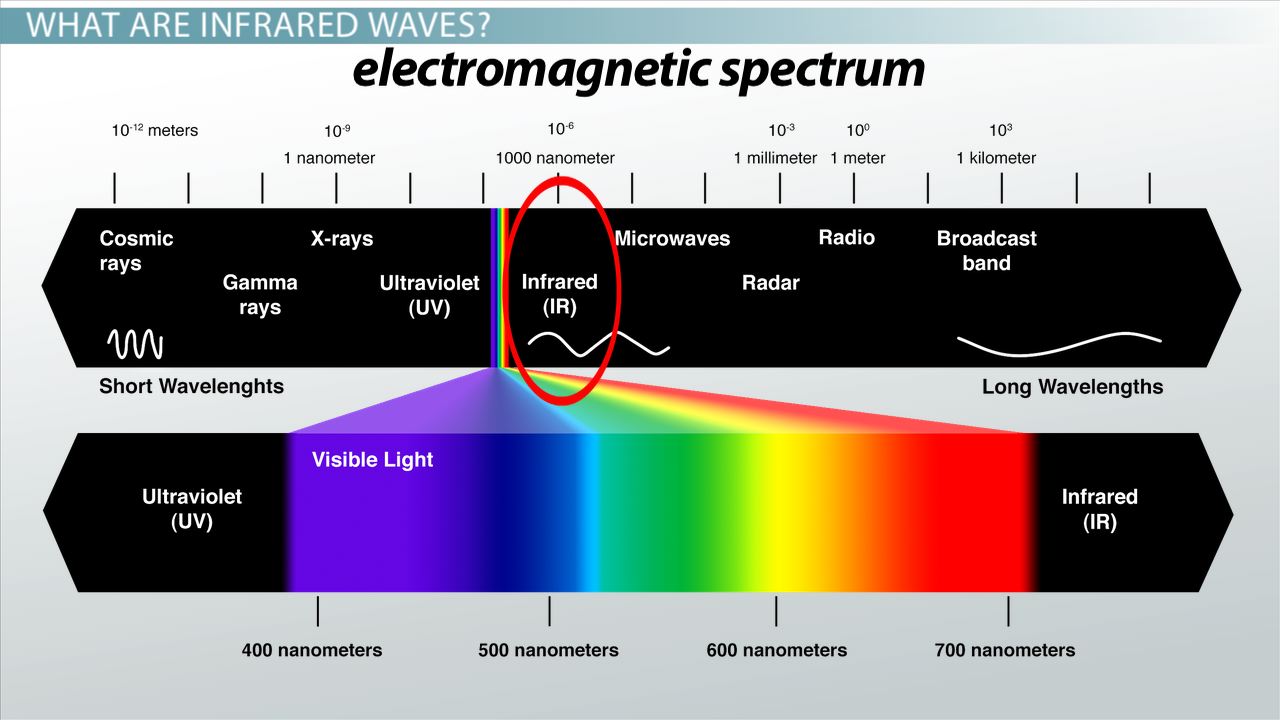
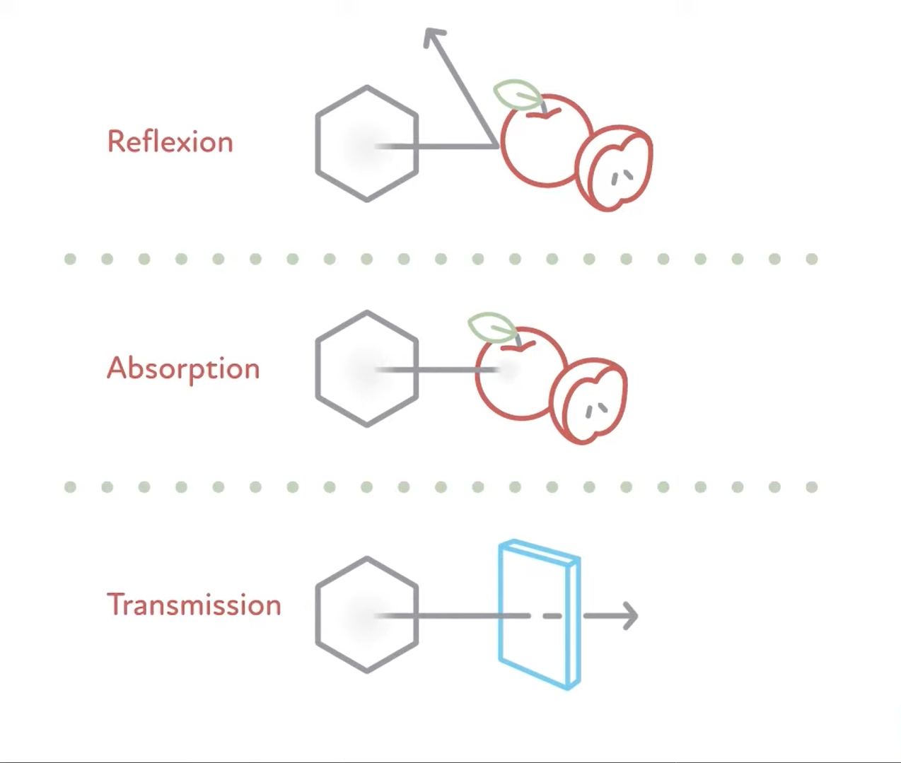
Visible light, also known as white light, ranges in wavelength from 0.4 to 0.8 micrometers (µm). It is mainly emitted by the sun and can be reflected, absorbed, or transmitted by objects. When white light strikes an object, some wavelengths are absorbed, while others are reflected. The reflected wavelengths determine the color we perceive.
Infrared Radiation has wavelengths ranging from 0.8 to 50 micrometers (µm), making it invisible to the human eye. Some animals, such as snakes, can detect infrared radiation, which corresponds to the thermal energy emitted by objects. Any object with a temperature above absolute zero (0 Kelvin or -273°C) emits infrared radiation, both during the day and at night.
Infrared Radiation and Temperature
When objects heat up, their radiation changes in two significant ways:
Increased Emission Across All Wavelengths
As an object becomes hotter, the object emits more radiation across all wavelengths. This makes the object appear brighter overall.
Shift in Peak Emission
The second thing that happens is that the peak of the emission shifts from the red all the way up through the blue. It goes on even further, the peak emission can shift beyond visible light into the ultraviolet region.
Wien’s Displacement Law
Wien’s Displacement Law describes the relationship between the temperature of a black body and the wavelength at which it emits the most radiation. This law is essential for understanding the thermal emission of objects. Wien’s Displacement Law is expressed as:
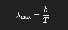
Where:
λmax is the wavelength of maximum emission (in meters).
𝑇 is the absolute temperature of the black body (in Kelvin, K).
𝑏 is Wien’s constant, approximately 2.897×10^−3 mK.
Note
λmax is the wavelength where the intensity of radiation is the highest, but the object still emits radiation at other wavelengths.
As the temperature of an object increases, the wavelength at which it emits the most energy decreases (i.e., shifts toward shorter wavelengths like visible or ultraviolet light). Conversely, cooler objects emit most of their radiation at longer wavelengths (infrared or microwave regions).
Bonus Information: Explanation of Why sunlight is white?
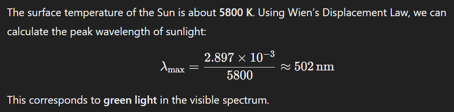
The Sun’s surface temperature is about 5800 Kelvin (K). By using Wien’s constant, the peak wavelength of sunlight from formula is approximately 502 nm. This corresponds to green light in the visible spectrum. So from Physics perspective, the Sun must appear green right? Before questioning Physics, let me finish my explanation.
Why the Sun Doesn’t Appear Green
This is more to do with Biology than Physics. Even though the Sun’s radiation peaks in the green region, it emits a broad spectrum of light that includes significant amounts of red, blue, and other colors. Our eyes have three types of cone cells sensitive to red, green, and blue light. Our eyes have not evolved to distinguish colour of highest intensity from colours of lower intensity, therefore the brain interprets the combination of all these wavelengths as white light.
The physics of blackbody radiation and Wien’s Law are accurate, but the perception of color is influenced by biology (human vision) and how our brain processes light from the entire spectrum.
The higher the temperature of a body, the closer its emitted radiation is to the visible light spectrum. Also, when a blacksmith heats a piece of iron until it is “white-hot,” it emits radiation across all visible wavelengths, making it appear white.

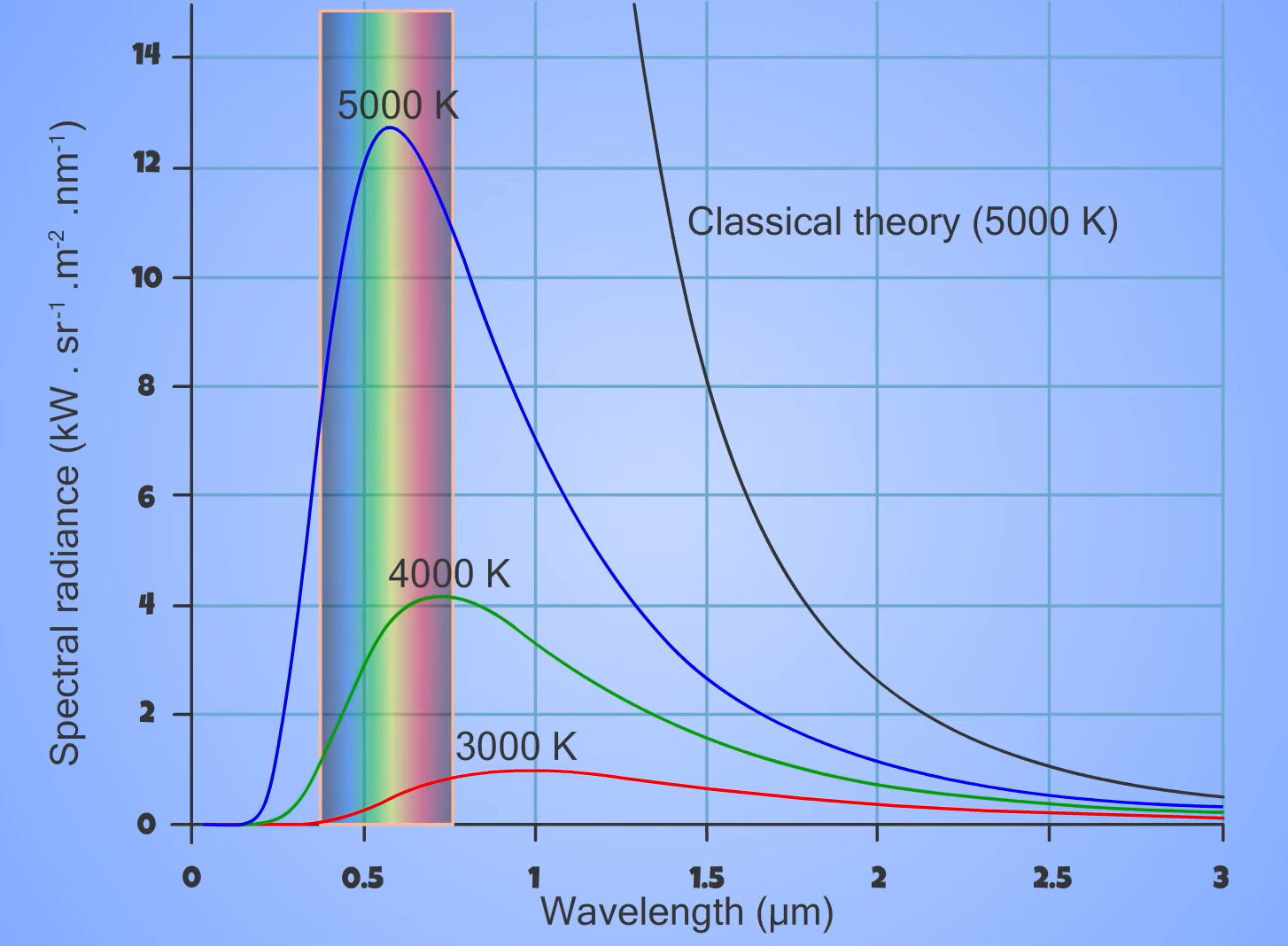
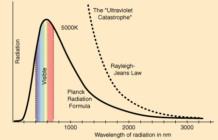
Rayleigh-Jeans law
The Rayleigh-Jeans Law is a formula that describes the spectral radiance of electromagnetic radiation emitted by a blackbody at a given temperature T. It is an approximation that applies at long wavelengths (or low frequencies) and is derived based on classical physics.

Where:
Bλ(T) is the spectral radiance (power emitted per unit area per unit wavelength).
c is the speed of light (≈ 3 × 10^8 m/s).
kB is Boltzmann’s constant (≈ 1.38 × 10^−23 J/K).
T is the absolute temperature of the blackbody in Kelvin.
λ is the wavelength.
The Rayleigh-Jeans Law accurately predicts the behavior of blackbody radiation at long wavelengths (low frequencies). When it comes to short wavelengths (high frequencies), the law predicts an infinite amount of energy, which contradicts experimental results. This discrepancy, known as the “ultraviolet catastrophe,” was one of the critical failures of classical physics and led to the development of quantum mechanics.
Ultraviolet Catastrophe
The ultraviolet catastrophe refers to a major problem in classical physics when predicting the radiation emitted by a blackbody at different wavelengths. This issue was particularly evident in the 19th century, and its resolution led to significant advancements in the field of quantum physics. The problem with the Rayleigh-Jeans Law was resolved by Max Planck, who introduced Planck’s Law of blackbody radiation in 1900. Planck’s Law accurately describes the spectral radiance across all wavelengths.
What Was the Problem?
Classical physics, particularly the Rayleigh-Jeans law, treated energy as continuous. According to classical theory, a blackbody could emit radiation at any frequency, and the energy emitted at a given frequency was not restricted. This led to the prediction that as the wavelength of radiation decreases (moving towards the ultraviolet region), the intensity would increase without bound—this is the ultraviolet catastrophe.
From Rayleigh-Jeans Law, as λ approaches 0 (shorter wavelengths), the intensity approaches infinity, which clearly contradicted experiments.
Solution by Planck
Planck realized that this continuous energy assumption was not correct. He proposed that energy was not emitted continuously, but rather in discrete packets, which he called quanta. Each quantum of energy was proportional to the frequency of the radiation:
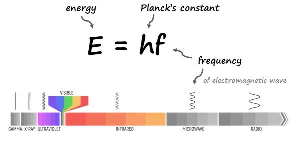
This assumption led to the idea that energy levels in a system could only take certain discrete values, rather than any value.
Planck’s Law
Using the concept of quantized energy, Planck derived a new formula for the spectral radiance of blackbody radiation, which replaced the Rayleigh-Jeans law. Planck’s Law describes the spectral distribution of electromagnetic radiation emitted by a black body at a given temperature. It provides a formula for calculating the spectral radiance, or the intensity of electromagnetic radiation at a specific wavelength and temperature. This law resolved the “ultraviolet catastrophe” predicted by classical physics, laying the foundation for quantum mechanics.
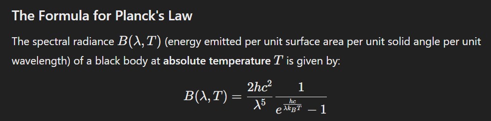
B(λ, T) = Spectral radiance (W·sr⁻¹·m⁻³)
h = Planck’s constant (6.626 × 10^−34 J·s)
c = Speed of light (3.00 × 10^8 m/s)
λ = Wavelength of radiation (m)
kB = Boltzmann’s constant (1.381 × 10^−23 J/K)
T = Absolute temperature (K)
From Planck’s Law, we can see that:
Wavelength Dependence
The amount of radiation emitted depends on the wavelength (λ).
Temperature Influence
As the temperature (T) increases, the peak of the emission curve shifts to shorter wavelengths (described by Wien’s Displacement Law).
Quantum Nature
The exponential term reflects the quantized nature of radiation, which was a breakthrough in explaining how energy is emitted in discrete packets (quanta).
At high frequencies (short wavelengths), the exponential factor dominates, which causes the intensity to decrease exponentially. This prevented the intensity from diverging, as classical theory had predicted. Instead of the radiation intensity growing infinitely at small wavelengths (the ultraviolet catastrophe), Planck’s formula predicted a smooth decrease in intensity.
At low frequencies (long wavelengths), Planck’s law approximates the Rayleigh-Jeans law, meaning it agrees with classical predictions for lower energy levels (where the temperature is not very high). This matched experimental data well for longer wavelengths.
Infrared cameras and thermal imaging devices rely on Planck’s law to measure temperature.
Stefan-Boltzmann’s Law
Stefan-Boltzmann’s Law describes the power radiated by a black body in terms of its temperature. It states that the total energy emitted per unit surface area of a black body is proportional to the fourth power of its absolute temperature.
For real materials (which are not perfect black bodies), we also multiply with emissivity of the material.
ϵ = Emissivity of the material (0 ≤ ϵ ≤ 1).
A perfect black body has an emissivity 𝜖 = 1, while a perfect reflector has 𝜖 = 0.
Higher temperatures lead to exponentially higher radiation due to the T^4 relationship. As an object’s temperature increases, it radiates more energy, and this radiation spans a range of wavelengths, including visible light. At higher temperatures, a greater proportion of the emitted radiation falls within the visible spectrum (Wien’s Displacement Law). This is why:
Hotter objects (like stars) appear brighter and often shift towards bluish-white colors.
Cooler objects emit less radiation and may glow red or not emit visible light at all.
Kirchhoff’s Law of Thermal Radiation
The law states that for any object at thermal equilibrium (balance), the emissivity of a surface is equal to its absorptivity. In simple terms,
“A good absorber is also a good emitter at the same wavelength and temperature.”
Emissivity (ε): As l explained, the fraction of radiation emitted by the surface compared to a perfect black body at the same temperature.
Absorptivity (α): The fraction of incident radiation absorbed by the surface.
At thermal equilibrium: 𝜀 = 𝛼
Perfect black body: Has an emissivity and absorptivity of 1 (ε = α = 1).
Reflective surfaces: Poor absorbers, so they are also poor emitters. A dark surface absorbs more radiation (high absorptivity) and thus emits more radiation at the same temperature. (Black Body in this context).
The Concept of a Black Body
Black Bodies and Emissivity
A black body is a theoretical object that absorbs all incident wavelengths and emits radiation solely based on its temperature. The efficiency with which real objects emit radiation is expressed by their emissivity, a value ranging from 0 to 1. Emissivity compares the radiance of a body to that of a black body.
An emissivity of 1 means the body emits radiation as efficiently as a black body. An emissivity of 0.5 means the body emits half the radiation of a black body.
Emissivity depends on an object’s physical properties. For example:
Human skin has a high emissivity of around 0.98.
Polished metals, like aluminum, can have emissivity values below 0.1, making them effective infrared reflectors (infrared mirrors).
Knowing an object’s emissivity allows for the accurate calibration of infrared devices, enabling precise temperature measurement.
How a Black Body Works
Absorption
A black body absorbs all electromagnetic radiation that strikes it, regardless of wavelength. This means it does not reflect or transmit any light—hence the term “black body”.
Emission
According to its temperature, a black body emits thermal radiation across a range of wavelengths. This emission follows Planck’s Law, which describes how the intensity and distribution of emitted radiation depend on temperature.
Thermal Radiation
Thermal radiation is the electromagnetic radiation emitted by any object with a temperature above absolute zero (0 Kelvin or -273.15°C). A black body emits the maximum possible radiation at every wavelength for its temperature.
Planck’s Law: Describes the spectral distribution of radiation emitted by a black body at a given temperature.
Wien’s Displacement Law: States that the wavelength at which a black body emits the most radiation shifts as its temperature changes. Higher temperatures shift the peak emission toward shorter wavelengths (e.g., visible light).
Stefan-Boltzmann Law: Indicates that the total power radiated by a black body is proportional to the fourth power of its temperature.
Bonus Information: Why are objects with emissivity near that of a black body more luminous?
When emissivity ϵ ≈ 1, it means the object is efficient emitter of radiation, this can be explained through Stefan-Boltzmann’s Law and the concept of emissivity. If an object has an emissivity near 1 (like a black body), it radiates more power compared to objects with lower emissivity at the same temperature. For instance, stars are excellent approximations of black bodies because they absorb and emit radiation extremely efficiently across a wide spectrum of wavelengths. Their high temperature (ranging from thousands to millions of Kelvin) means they radiate a huge amount of power according to Stefan-Boltzmann’s Law. Their emissivity is very close to 1 because they don’t reflect much radiation — almost all the energy is emitted as light and other forms of radiation. Higher temperature results in exponentially higher radiation (T - P relationship). This combination of high temperature and high emissivity makes objects like stars incredibly luminous (they emit vast amounts of light).

Discovery of Infrared Radiation
Up until 1800, visible light was the only known part of the electromagnetic spectrum that’s when astronomer Sir William Herschel discovered a whole new world of infrared radiation. This discovery marked a significant milestone in understanding the electromagnetic spectrum beyond visible light.
Using a Prism to Split Sunlight
Herschel passed sunlight through a glass prism, which split the white light into its constituent colors (a spectrum of red, orange, yellow, green, blue, indigo, and violet). In his observations of sunlight, Herschel experimented with colors of light and noticed each one passed a different amount of heat.
Measuring Heat in Different Colors
To measure the heat associated with each color of light, he used thermometers with blackened bulbs. The blackened bulbs helped absorb more heat for accurate temperature readings.

Observation of Red Light
Herschel noted that the temperature increased as he moved the thermometer from blue to red. The temperature reading was highest in the red part of the spectrum.
Beyond Red Light
Out of curiosity, Herschel extended his thermometer just beyond the red part of the spectrum where no visible light was present. To his surprise, the thermometer showed a temperature even higher than in the visible red light region.
Herschel concluded that there must be an invisible form of radiation beyond red light, which was responsible for the increased heat. He named this new discovery “infrared radiation”, from the Latin words:
“Infra” = below
“Red” = refers to its position below red in the visible spectrum.
This experiment revealed that the electromagnetic spectrum extends beyond visible light, laying the foundation for understanding other types of electromagnetic waves such as ultraviolet (UV), X-rays, and radio waves. This breakthrough paved the way for future discoveries in the electromagnetic spectrum, leading to innovations in communication, astronomy, and medicine. Infrared radiation is now used in various fields like night vision, thermal imaging, remote sensing, and medical diagnostics.
When I first learned about Wien’s displacement law, I was fascinated to discover that the Sun’s peak wavelength is in the green spectrum of visible light. However, then I came across an experiment that left me puzzled— How infrared radiation feel hotter than green light? How can this be? If the Sun’s peak wavelength is in the visible spectrum (around green), in addition, green light has more energy than infrared because it has a shorter wavelength and higher frequency. Then, why does infrared radiation feel hotter to us than visible light?
Before reading this, have you ever thought about this contradiction? It’s one of those moments where science makes us stop and think deeper about what’s really happening. Let’s explore this intriguing question together.
Why Infrared Feels Hotter Even Though Green Is the Peak Wavelength?
To understand this, we need to investigate several aspects of sunlight.
1. Wavelength and Heat Emission
As we explained, according to Wien’s Displacement Law, the peak wavelength of radiation emitted by an object depends on its temperature. The Sun has a surface temperature of around 5,500°C (5,800 K), which places its peak wavelength in the visible light range, more specifically in green light. However, the Sun emits radiation across a broad spectrum, not just at the peak wavelength. While the peak of the Sun’s radiation is in the visible spectrum, it emits far more energy overall in the infrared spectrum. The total intensity of radiation emitted by the Sun spans from infrared to ultraviolet, with infrared radiation covering a much larger range of wavelengths than visible light. So, while the peak is in the visible range, the total emitted energy in the infrared is greater because of the larger range of wavelengths in the infrared (0.7 µm to 1 mm) and the nature of thermal energy. As it travels through space and reaches Earth, infrared radiation is primarily responsible for warming us up, even though it’s invisible to the naked eye.
2. How They Relate But Don’t Contradict
Herschel’s discovery of infrared radiation was about the heat carried by light. He found that infrared radiation (beyond red) carries more thermal energy than visible light because the Sun emits a lot of energy in the infrared.
On the other hand, Black body radiation refers to the color of emitted light, which shifts from red to blue as the temperature of the object increases. Blue light corresponds to a hotter temperature, but it does not necessarily mean it carries more heat in the way infrared does. In the context of glowing objects or black body radiation, for instance, blue light corresponds to higher temperatures than red light. However, Herschel’s experiment dealt with solar radiation at Earth’s surface, where the sun’s emission spectrum delivers more heat energy in the red and infrared range. Blue light is emitted by hotter objects, meaning it comes from objects with higher temperatures (like blue stars), but it doesn’t carry heat as effectively as infrared. Infrared radiation (even though it corresponds to lower-energy photons) is more abundant in the Sun’s radiation and is much better at carrying heat to Earth.
3. Why Infrared Transfers Heat Better
Infrared radiation is effective at transferring heat because it interacts efficiently with molecules in the Earth’s atmosphere and on surfaces. When infrared radiation strikes an object, its energy is absorbed and converted to heat. Even though visible light and ultraviolet light carry more energy per photon (especially the blue and UV parts), they don’t transfer heat as effectively because they interact differently with materials (e.g., UV tends to cause chemical changes rather than heat).
IR Remote
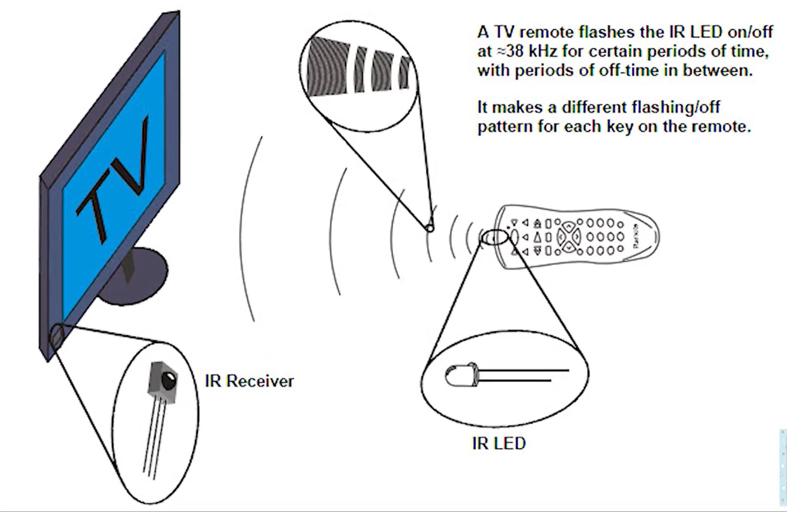
An IR (infrared) remote control works by sending coded infrared light signals to control electronic devices such as TVs, air conditioners, and audio systems.
Key Components of an IR Remote
IR LED (Infrared Light-Emitting Diode): Emits infrared light signals.
Microcontroller: Generates the signal patterns for specific commands (like changing channels).
Buttons: When pressed, they send input to the microcontroller.
Power Source: Usually batteries.
How It Works
Signal Generation
Each button press corresponds to a specific binary code or signal pattern (e.g., turning the TV off or changing the volume). The microcontroller generates these codes.
Modulation
The signal is modulated with a carrier frequency, typically 38 kHz, to avoid interference from ambient infrared sources (like sunlight or indoor lighting).
Transmission
The IR LED emits the modulated infrared signal in pulses that represent the command code.
Reception
The receiving device has an IR sensor that detects the modulated IR light. The sensor demodulates the signal and sends the decoded command to the device’s processor.
Execution
The device responds by executing the corresponding action, such as turning on, changing the channel, or adjusting the volume.
Technical Details
Range: Typically 5-10 meters; requires a direct line of sight.
IR Wavelength: Around 940 nm (not visible to the human eye).
Encoding Schemes: Popular protocols include NEC, Sony SIRC, and RC-5, each with its own signal format.
Each protocol defines how data is structured, including headers, bit lengths, and commands.
Structure of an IR Command
An IR command typically has at least one of the following components:
Header
A unique signal pattern at the beginning to indicate the start of a command.
Address
Specifies the target device (e.g., a specific TV model or brand).
Command Code
The specific function (e.g., power on, volume up, channel change).
Checksum or Repeat Code (Optional)
Ensures data integrity or indicates a repeated command when the button is held down.
Common Applications of IR Commands
TV Remote Controls: Power, volume, and channel changes.
Home Automation: Controlling lights, fans, or appliances.
Robotics: Controlling robot movements with a remote.
Custom Electronics Projects: IR-based communication between devices.
IR Communication Protocol
The NEC (Nippon Electric Company) protocol is a popular infrared (IR) communication protocol commonly used for remote controls in consumer electronics like TVs, audio systems, and other appliances. It is designed to transmit commands via IR signals in a structured and reliable format.
Key Features of the NEC Protocol
Carrier Frequency
The IR signal is modulated at a carrier frequency of 38 kHz, which helps the receiver differentiate between the transmitted signal and ambient IR noise.
Data Format
The protocol transmits data in a series of pulses and spaces, representing binary “1” and “0”.
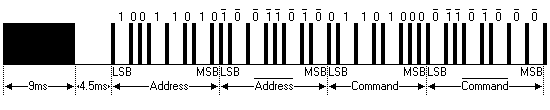
Frame Structure
An NEC protocol message consists of four key components:
Leader Code: A long pulse (9 ms) followed by a long space (4.5 ms). This signals the start of a transmission.
Data Bits
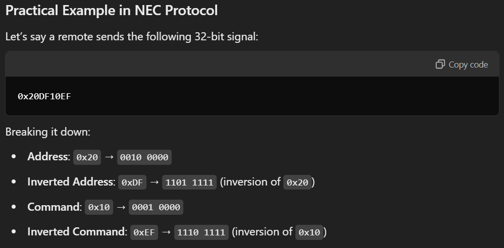
The actual command data, typically 32 bits divided into four 8-bit segments:
Address (8 bits): Identifies the device to be controlled.
Address Inverted (8 bits): Inverted bits of the address for error checking.
Command (8 bits): Specifies the action or function (e.g., volume up, channel change).
Command Inverted (8 bits): Inverted bits of the command for error checking.
Stop Bit: A short pulse (562.5 µs) after the data, indicating the end of the transmission.
Why Protocol use Inverted Addresses?
The inverted address in an IR remote protocol, such as the NEC protocol, is a way to ensure data integrity and detect errors.
What is the Inverted Address?
The inverted address is the bitwise complement of the address.
This means every bit in the inverted address is the opposite of the corresponding bit in the address:
If a bit in the address is 1, the same bit in the inverted address is 0.
If a bit in the address is 0, the same bit in the inverted address is 1.
Example
Address: 0b11001100
Inverted Address: 0b00110011 (each bit is flipped)
Why Use an Inverted Address?
Error Detection
The inverted address helps verify that the data was received correctly. If the address and its inversion don’t match, an error likely occurred during transmission.
Data Integrity
By sending both the original and inverted values, the receiving system can confirm the accuracy of the received signal.
How to Check Inverted Address in Code?
When decoding an NEC IR signal in Arduino:
1
2
3
4
5
6
7
8
9
10
11
12
13
if (IR.decode()) {
  unsigned long rawData = IR.decodedIRData.decodedRawData;
  uint8_t address = rawData >> 24;  // Extract the first 8 bits (Address)
  uint8_t invertedAddress = (rawData >> 16) & 0xFF;  // Extract the next 8 bits (Inverted Address)

  if (address == (invertedAddress ^ 0xFF)) {
    Serial.println("Address and Inverted Address match!");
  } else {
    Serial.println("Error: Address mismatch.");
  }

  IR.resume();
}
Code Explanation
1
if (IR.decode()) {
This checks if an IR signal has been received and successfully decoded. If IR.decode() returns true, the IR data is available for processing.
1
unsigned long rawData = IR.decodedIRData.decodedRawData;
rawData stores the entire 32-bit value received from the IR remote. As we explained, this 32-bit data typically contains:
Address (8 bits)
Inverted Address (8 bits)
Command (8 bits)
Inverted Command (8 bits)
Right Shift(») Operator
Right Shift(») is a binary operator that takes two numbers, right shifts the bits of the first operand, and the second operand decides the number of places to shift.
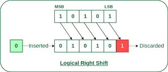
1
uint8_t address = rawData >> 24;
Extract the First 8 Bits
The right shift operation (» 24) moves the bits of rawData 24 positions to the right, effectively discarding the lower 24 bits. The result of the shift keeps only the highest (first) 8 bits of the original 32-bit value. Since address is declared as uint8_t (an 8-bit data type), it will only store those 8 bits.
Example
Suppose rawData is:
1
0xE619FF00
In binary it is:
1
1110 0110 0001 1001 1111 1111 0000 0000
When you do rawData » 24:
1
0000 0000 0000 0000 0000 0000 1110 0110
Now, storing it in uint8_t address:
1
address = 0xE6  // The highest 8 bits of rawData
Bitwise Operators
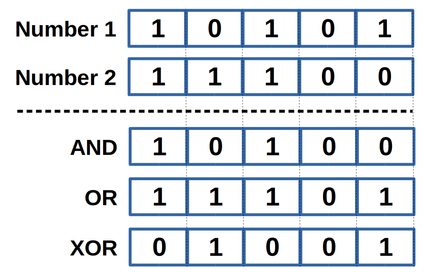
The & (bitwise AND) in C takes two numbers as operands and does AND on every bit of two numbers. The result of AND is 1 only if both bits are 1.
The | (bitwise OR) in C takes two numbers as operands and does OR on every bit of two numbers. The result of OR is 1 if any of the two bits is 1.
The ^ (bitwise XOR) in C takes two numbers as operands and does XOR on every bit of two numbers. The result of XOR is 1 if the two bits are different.
1
uint8_t invertedAddress = (rawData >> 16) & 0xFF;
Right shift by 16 bits (» 16) moves the next 8 bits (the inverted address) to the least significant position.
Masking with 0xFF (& 0xFF) ensures that only the lower 8 bits are kept, discarding any higher bits.
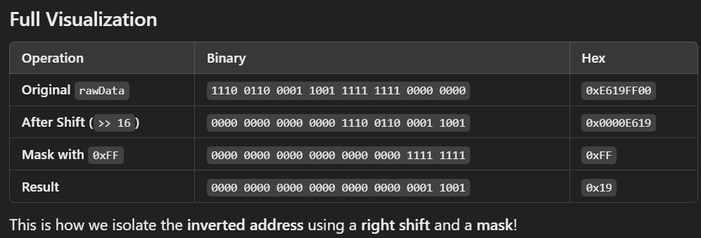
Explanation of Masking
Let’s assume rawData is:
1
rawData = 0xE619FF00
In binary, it looks like this:
1
2
3
  1110 0110     0001 1001        1111 1111       0000 0000
| Address  | Inverted Address |  Command   |  Inverted Command |
    0xE6          0x19              0xFF              0x00
When we shift rawData right by 16 bits (» 16), we get:
1
2
3
1110 0110 0001 1001 1111 1111 0000 0000  (original rawData)
↓↓↓↓ ↓↓↓↓ ↓↓↓↓ ↓↓↓↓ ↓↓↓↓ ↓↓↓↓ ↓↓↓↓ ↓↓↓↓  (shift right by 16)
0000 0000 0000 0000 1110 0110 0001 1001
Now, the inverted address (0001 1001) is in the least significant byte.
Masking with 0xFF
1
0000 0000 0000 0000 0000 0000 1111 1111 // (0XFF)
When we perform the bitwise AND (&) with 0xFF, we keep only the least significant byte:
1
2
3
4
  0000 0000 0000 0000 1110 0110 0001 1001  (after right shift)
& 0000 0000 0000 0000 0000 0000 1111 1111  (mask with 0xFF)
-----------------------------------------
  0001 1001                              → 0x19
invertedAddress now contains 0x19 (the second byte of the original rawData).
1
 if (address == (invertedAddress ^ 0xFF)) {
Check Address and Inverted Address
invertedAddress ^ 0xFF flips all the bits of invertedAddress (bitwise XOR with 0xFF). When invertedAddress all bits are flipped, if the transmission was successful, it should be equal to address. This checks if the address and invertedAddress are correct inverses of each other. If they match, the data is likely valid.
If the address and inverted address match, a confirmation message is printed. An error message is printed if there’s a mismatch.
1
IR.resume();
Prepares the IR receiver to handle the next signal.
Summary of this code
Receives an IR signal and decodes it. Extracts the address and inverted address from the rawData. Checks if the address and inverted address are valid by confirming they are inverses of each other. Prints a message based on whether the check passes or fails. Resumes listening for the next IR signal.
This is a common way to ensure data integrity when dealing with IR signals using the NEC protocol or similar protocols that use address verification.
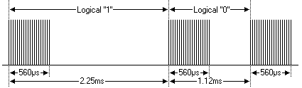
Pulse Distance Encoding
The NEC protocol uses Pulse Distance Encoding to represent binary 0s and 1s. The pulses are always 562.5 µs long, but the spaces (gaps) that follow them differ for 0 and 1. With this protocol the LSB is transmitted first. The total transmission time is constant because every bit is repeated with its inverted length.
27ms to transmit both the 16 bits for the address (address + inverse) and the 16 bits for the command (command + inverse).
This comes from each of the 16 bit blocks ultimately containing eight ‘0’s and eight ‘1’s - giving (8 * 1.125ms) + (8 * 2.25ms).
If you’re not interested in this reliability you can ignore the inverted values, or you can expand the Address and Command to 16 bits each.
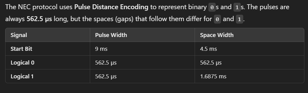
Start Bit
A 9 ms pulse followed by a 4.5 ms space.
Data Bits
Each bit is sent as a 562.5 µs pulse followed by a space:
Logical ‘0’ – a 562.5µs pulse burst followed by a 562.5µs space, with a total transmit time of 1.125ms.
Logical ‘1’ – a 562.5µs pulse burst followed by a 1.6875ms space, with a total transmit time of 2.25ms.
Stop
After all bits are sent, a final 562.5 µs pulse.
Repeat Signals
When a button on the remote control is first pressed, the full 32-bit command frame (address, address inverted, command, command inverted) is transmitted once. If the button remains pressed, the remote does not retransmit the full 32-bit frame repeatedly. Instead, it sends a simpler repeat code at intervals of approximately 110 ms.
Repeat Signal Format:
9 ms AGC (Automatic Gain Control) burst: A long pulse for receiver synchronization.
2.25 ms space: A pause to separate the AGC burst from the next signal.
562.5 µs burst: A short pulse that acts as a marker to complete the repeat code.
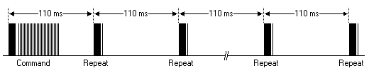
Purpose of the Repeat Code
The repeat code tells the receiving device that the user intends to continue the same action (e.g., increasing volume). By avoiding retransmission of the full command, the protocol saves power in the remote control, reduces processing overhead in the receiving device and minimizes IR signal interference in the environment.
Example Scenario
Initial Action: You press the “Volume Up” button on your TV remote. The remote sends the full NEC command frame corresponding to “Volume Up.”
Holding the Button: If you keep holding the button, the remote sends a repeat code every 110 ms, indicating the same action should continue.
Extended NEC protocol
The extended NEC protocol was introduced to allow for more devices by increasing the address space. In this protocol:
Both the low byte and high byte of the address are independent 8-bit values.
Address = High Byte + Low Byte (total 16 bits).
However, there’s a special case:
If the low byte of the extended address is the exact inverse of the high byte, it is not a valid extended address because it matches the structure of the standard NEC protocol. When the low byte is the exact inverse of the high byte, the receiver cannot distinguish whether the signal follows the standard NEC protocol or the extended NEC protocol. To avoid ambiguity, such address combinations are reserved as invalid extended addresses. In the extended NEC protocol, the full 16-bit address space allows for 65,536 possible addresses. Out of these, 256 combinations (where Low Byte = ~High Byte) are invalid because they conflict with the standard NEC protocol. A receiver implementing both standard and extended NEC protocols must check the address structure to determine which protocol is being used:
If Low Byte = ~High Byte, treat it as standard NEC.
Otherwise, treat it as extended NEC.
Why No Inverse Checking in Extended NEC?
Larger Address Space
The extended NEC protocol is designed to support up to 65,280 unique addresses (excluding the 256 ambiguous ones). Adding a bitwise inverse relationship would halve this space, which defeats the purpose of “extending” the address range.
Protocol Evolution
The extended protocol assumes that devices using it have robust error-checking mechanisms (e.g., checksum, command validation) beyond the address bytes.
The command redundancy is still preserved. Therefore each address can still handle 256 different commands.
Photos are taken from SB Projects.
IR Remote Library can affect PWM Capability
In many Embedded projects, PWM (Pulse Width Modulation) is a crucial technique used to control the brightness of LEDs, motor speeds, and even audio signals. PWM works by adjusting the amount of time a signal is on versus off within a set period, allowing for smooth control over various devices.
However, when incorporating IR remote control functionality using the IRremote library, it can inadvertently affect PWM on specific pins. This is because the IRremote library utilizes hardware timers to decode signals, and those timers are also responsible for controlling PWM on certain pins. As a result, the library may override or interfere with PWM functionality, particularly on pins linked to timers it uses.
While you may not be using PWM in your project, understanding how the IR library affects timers and PWM can be useful in optimizing your project and troubleshooting potential conflicts.
IRremote Library and Timer Conflicts
The IRremote library typically uses Timer2 on the Arduino (specifically on the ATmega328P chip) to handle infrared signal decoding. However, Timer2 is also responsible for controlling PWM signals on pins 3 and 11. When the IRremote library takes control of Timer2, it disables the PWM functionality on these pins. As a result, if you’re using these pins for PWM, activating the IRremote library may cause these pins to stop functioning as PWM outputs. This conflict can be avoided by either changing the PWM pins or modifying the library’s timer usage. These pins can no longer produce PWM output because the timer is now dedicated to handling IR signal decoding.

The image shows the pins used by each type of microcontroller.
L298N Motor Driver Explained
The L298N is a dual H-bridge motor driver IC that allows you to control two DC motors or one stepper motor. It’s a versatile and widely used component for robotics and other motor control applications.
Transistor Explained
A transistor is a semiconductor device used to amplify or switch electronic signals and electrical power. It is one of the most fundamental building blocks of modern electronic devices. Transistors are made from semiconductor materials, typically silicon or germanium, and are essential in nearly all electronic devices, from simple circuits to complex integrated circuits (ICs).
Types of Transistors
Bipolar Junction Transistors (BJTs)
A BJT is a type of transistor that relies on the flow of both majority and minority charge carriers (hence the name “bipolar”) to amplify or switch electrical signals. It is one of the oldest and most widely used semiconductor devices.
Structure of BJT
A BJT has three regions:
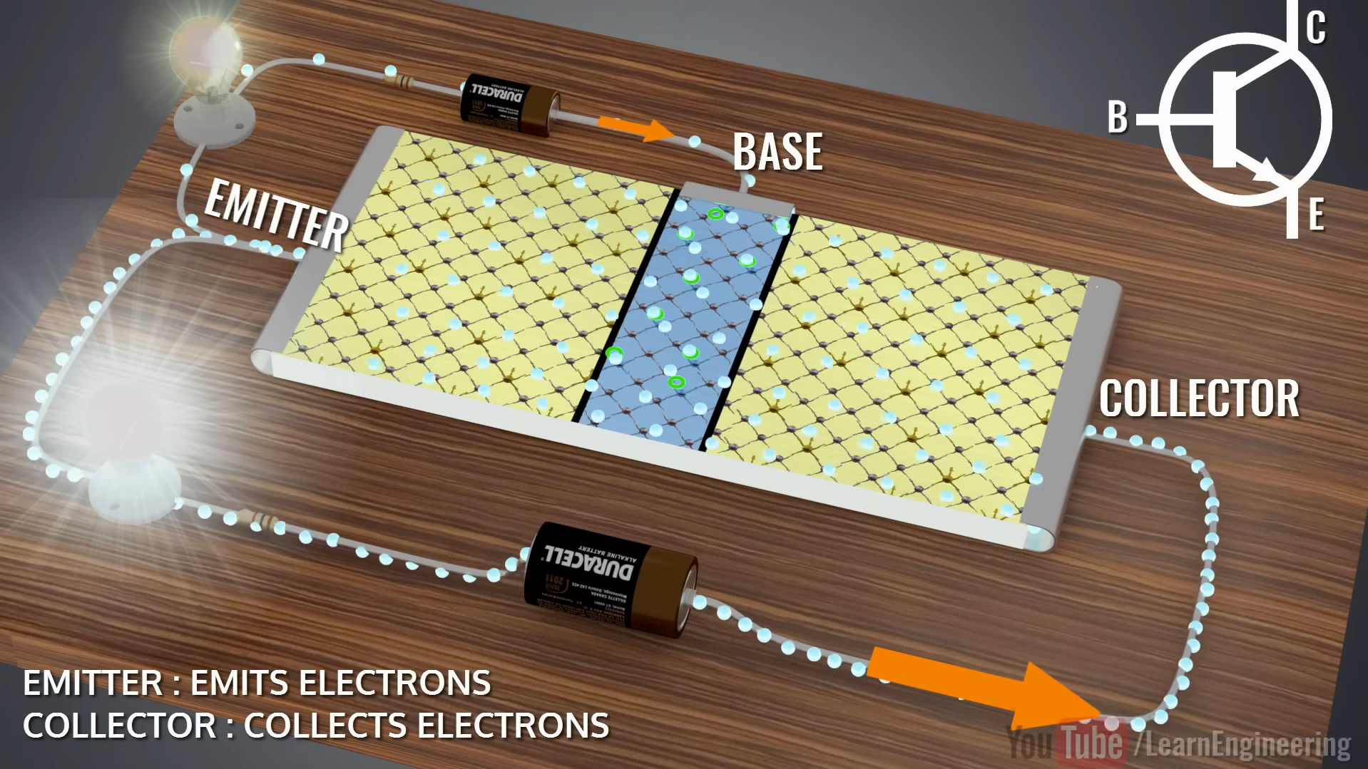
Emitter (E): Highly doped to provide a large number of charge carriers.
Base (B): Thin and lightly doped, located between the emitter and collector.
Collector (C): Moderately doped and larger in size to handle the heat and collect charge carriers.
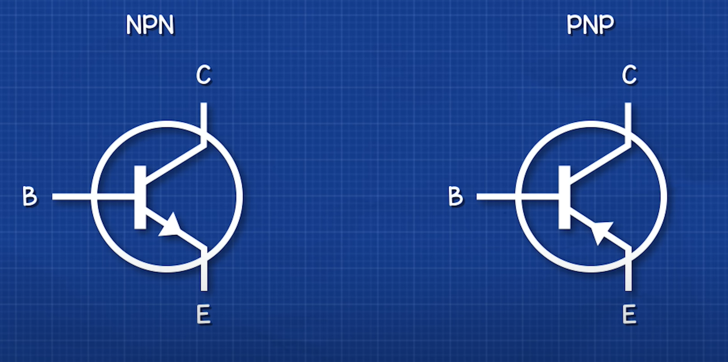
Composed of three layers of doped semiconductor material. It has 2 types:
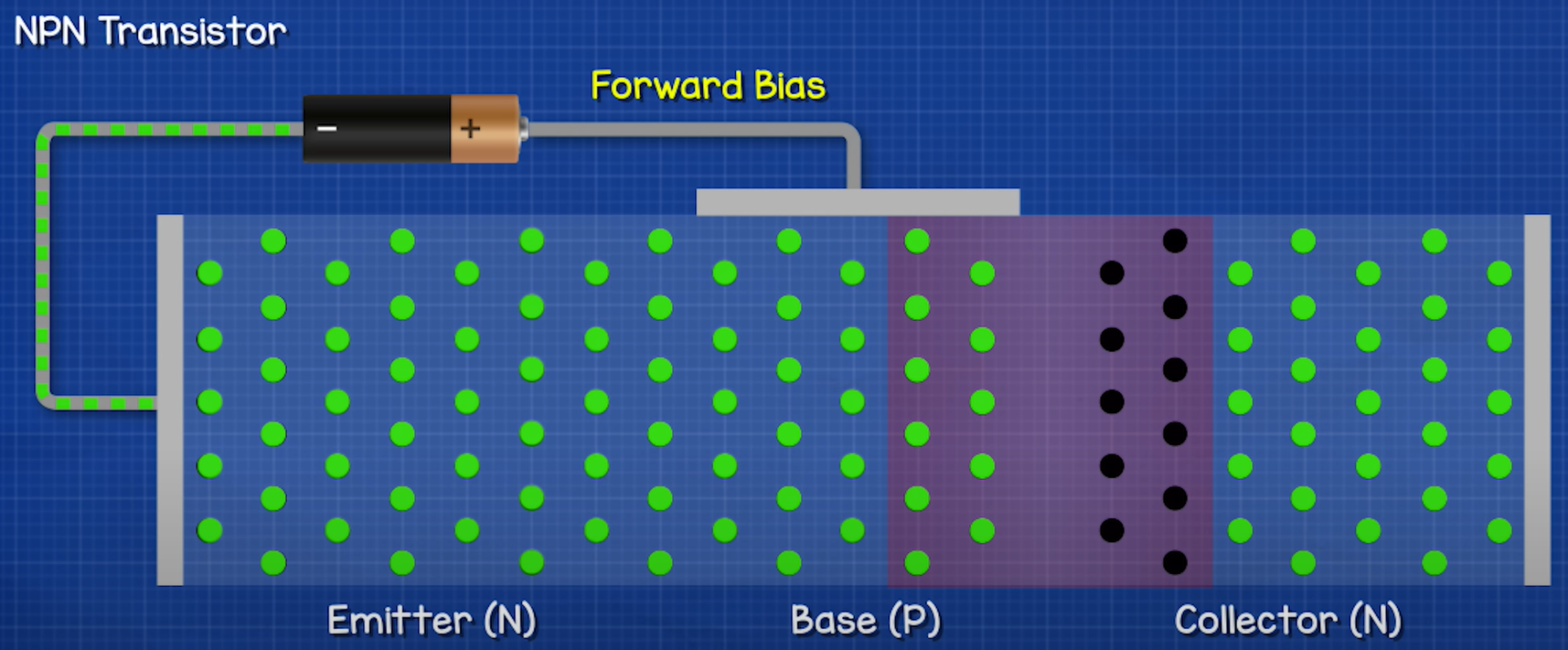
NPN: Made of two n-type materials separated by a p-type material.
PNP: Made of two p-type materials separated by an n-type material.
Operates using both electrons and holes as charge carriers. Current flows between collector and emitter, controlled by the base current.
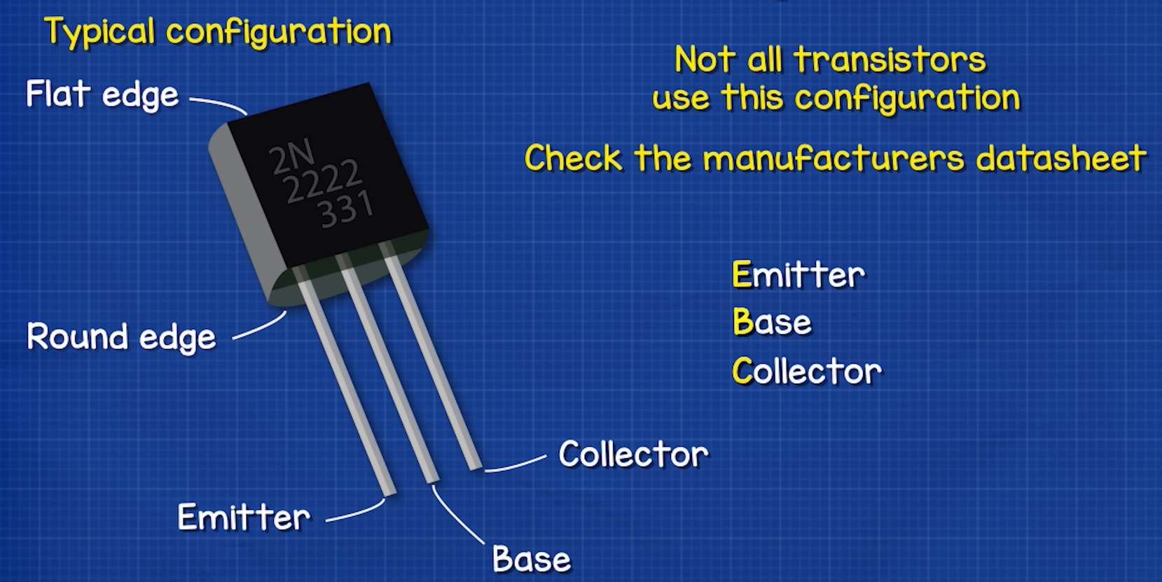
The arrow on the emitter indicates the direction of conventional current, helping us correctly connect it in circuits.
How a Transistor Works at the Atomic Level
Water Flow Analogy
To better understand how transistors work, let’s use a water flow analogy. Imagine water flowing through a main pipe, but its flow is blocked by a movable disc. Now, introduce a smaller control pipe connected to the main one, with a swing gate inside. This swing gate operates a pulley that lifts the disc in the main pipe. However, the gate is slightly heavy, so a small trickle of water won’t be enough to move it. A certain minimum amount of water is required to force the gate open. As more water flows through the small pipe, the gate opens wider, pulling the disc higher and allowing more water to pass through the main pipe. This is similar to how an NPN transistor operates, where a small input current controls a much larger current flow.
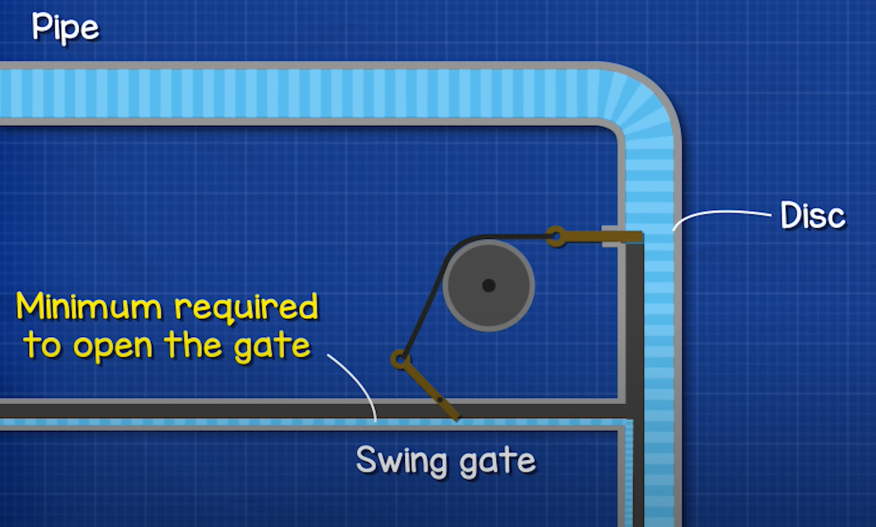
With this analogy in mind, let’s explore the working principle of transistors in detail.
Atomic Level Explanation
When a transistor is formed, it consists of PN junctions (like a diode) between its regions: Emitter, Base, and Collector. These PN junctions create a depletion region and a potential barrier due to charge carrier movement.
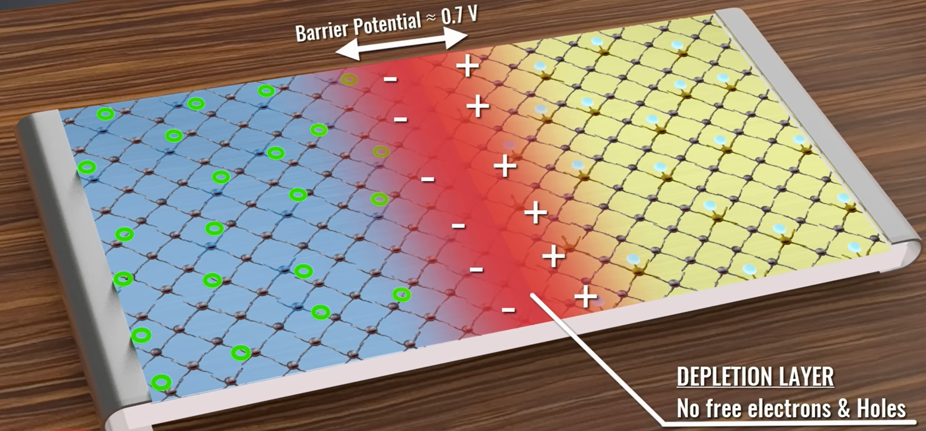
Depletion Region
When the P-type (Base) and N-type (Emitter/Collector) materials come into contact, free electrons from the N-region diffuse into the P-region, while holes from the P-region diffuse into the N-region. As a result, a charge-free zone (depletion region) forms at the junction, with immobile positive ions in the N-region and negative ions in the P-region. This depletion region acts as an insulating layer, preventing further charge carrier movement unless an external voltage is applied.
Potential Barrier
Due to the separation of charges in the depletion region, an electric field forms, creating a potential difference called the potential barrier. This barrier prevents further electron movement from the N-region to the P-region unless sufficient energy is supplied. For Silicon transistors, this barrier is approximately 0.7V, and for Germanium transistors, it is around 0.3V. Without this 0.7V, the transistor remains in the cutoff region (OFF state), and no significant current flows between the Collector and Emitter.
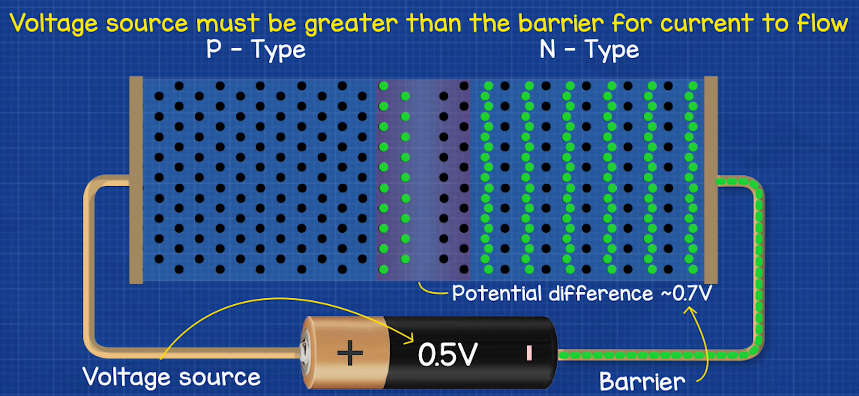
Forward Bias
When a PN junction is forward biased:
The positive terminal of the battery is connected to the p-side, and the negative terminal is connected to the n-side. This reduces the depletion region and lowers the potential barrier, allowing charge carriers (electrons and holes) to move across the junction. As a result, current flows easily through the PN junction. This is the conducting state of the diode. Resistance is low.
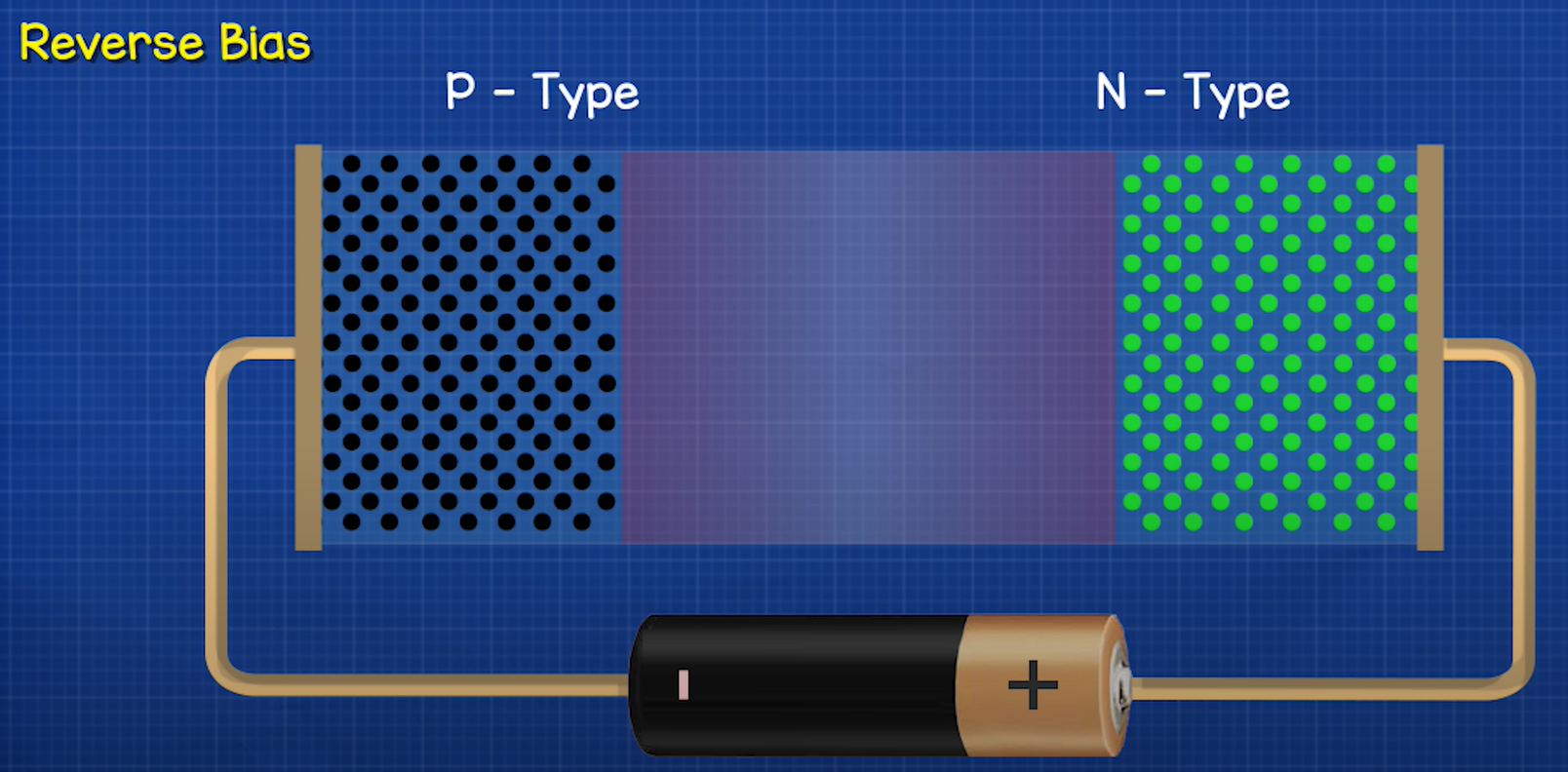
Reverse Bias
When a PN junction is reverse biased:
The positive terminal of the battery is connected to the n-side, and the negative terminal is connected to the p-side. This increases the depletion region and raises the potential barrier, preventing the flow of majority charge carriers. Only a tiny leakage current flows due to minority carriers, making it practically non-conducting. If the reverse voltage is too high, breakdown can occur (Zener or avalanche breakdown), leading to a sudden surge of current. Resistance is high.

What is actually happening?
In an NPN transistor, there are two layers of N-type material, forming two PN junctions and creating two potential barriers that prevent current from flowing under normal conditions.
The Emitter (N-type) is heavily doped, meaning it has a high concentration of free electrons.
The Base (P-type) is really thin and lightly doped on purpose so that there is a low chance of electrons falling into a hole, so it contains fewer holes for recombination.
The Collector (N-type) is moderately doped, resulting in a lower concentration of free electrons compared to the emitter.
If we connect a battery across the Base and Emitter, with the positive terminal connected to the P-type Base, it creates a forward bias in the Base-Emitter junction. This forward bias reduces the depletion region and lowers the potential barrier, provided the voltage is at least 0.7V for a silicon transistor. As the barrier diminishes, electrons from the heavily doped N-type Emitter rush into the lightly doped P-type Base. Some of these electrons recombine with holes in the Base and are attracted toward the positive terminal of the battery.
However, as we said, because the Base is very thin and lightly doped, only a small Base current flows out of the Base pin, as most electrons from the Emitter do not recombine with holes in the Base. This leaves an excess of electrons in the P-type Base material, which are then attracted toward the Collector due to its higher voltage.
To explain it more clearly, if we then connect another battery between the Emitter and the Collector, with the positive terminal connected to the Collector, the negatively charged electrons in the Collector will be attracted toward the positive terminal of this battery, creating a reverse bias across the Collector-Base junction. In a reverse-biased junction, electrons and holes are pulled back to their respective regions, widening the depletion region and preventing current flow under normal conditions. However, in an NPN transistor, there is already an excess of electrons in the lightly doped P-type Base due to the forward bias of the Base-Emitter junction.
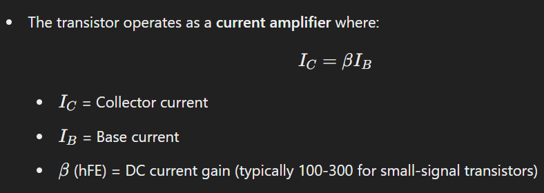
Since the Collector-Base voltage is higher, these excess electrons in the Base are strongly attracted toward the Collector. Many of them are pulled across the Collector-Base junction and into the Collector, continuing their flow into the battery’s positive terminal. As more electrons are drawn across, a large current flows from the Collector to the Emitter, allowing the transistor to act as a current amplifier or a switch. This is how a small Base current can control a much larger Collector-Emitter current, making the transistor a powerful electronic component.
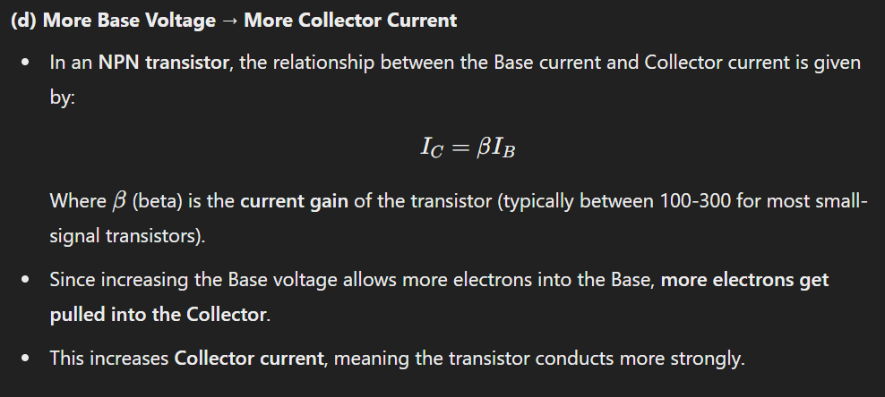
A higher voltage on the Base pin increases the Base current, which further reduces the depletion region at the Base-Emitter junction and allows more electrons to flow from the Emitter into the Base. The Base region is very thin and lightly doped, meaning it has very few holes for recombination. Because of this, only a small fraction of electrons recombine with holes in the Base (this forms the small Base current 𝐼𝐵).
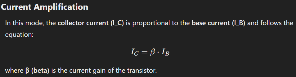
Since the Collector-Base junction is reverse biased, as more electrons enter the Base (due to the increased Base voltage), most of these electrons do not recombine in the Base but are instead pulled across the Collector-Base junction due to the strong electric field. This results in an increase in the Collector current (𝐼𝐶), meaning the transistor is fully turned on, allowing maximum current flow from Collector to Emitter. So if we increase the base current the collector current will increase proportionally.
Note : The voltage across a component is simply the difference between its terminals, even if different supplies exist. The voltage drop created by the 0.7V power supply on the transistor still affects the main circuit’s calculations, even though the 9V supply is different.
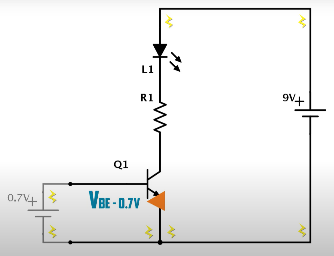
Why Does This Happen?
Voltages are always relative to a reference point (usually ground). A voltage drop means a potential difference between two points, and Kirchhoff’s Voltage Law (KVL) still applies (the total voltage supplied must equal the sum of all voltage drops), even if different power supplies exist. If the two supplies share a common ground, then they interact electrically, affecting the same circuit.
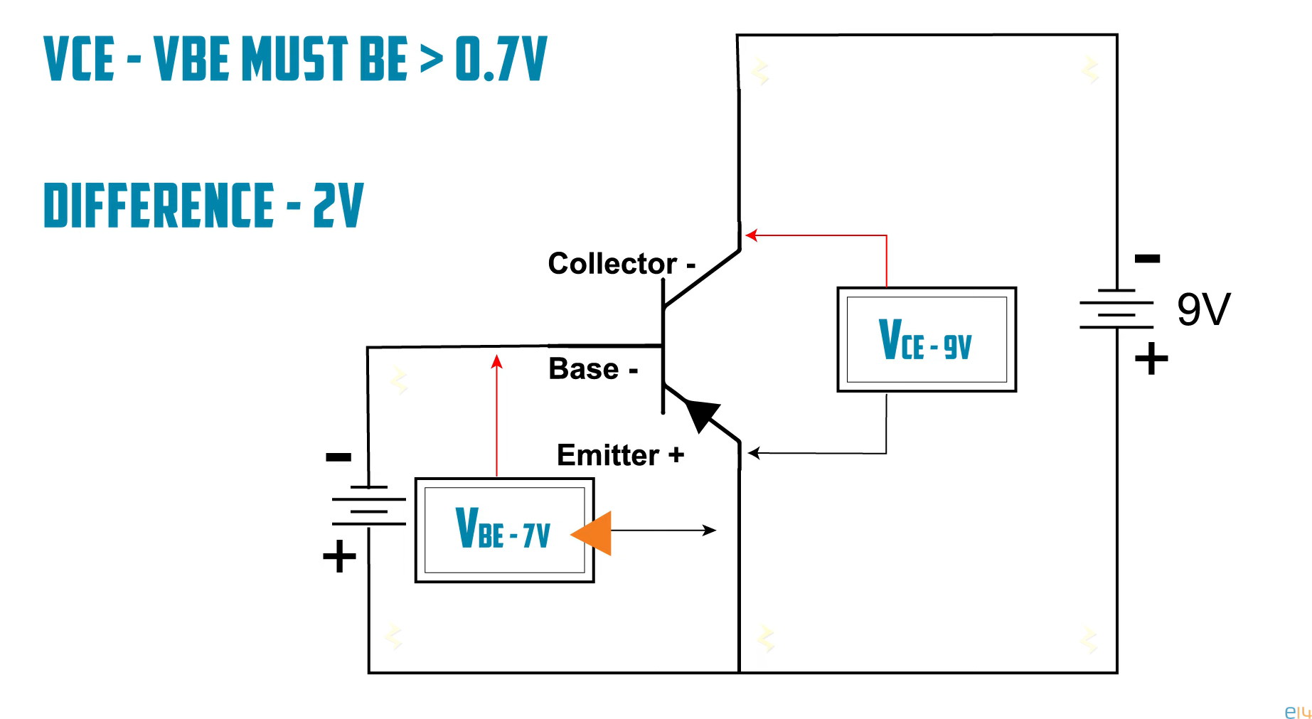
How PNP Transistor Works?
For a PNP transistor, instead of needing a minimum of 0.7V on the base (as in an NPN transistor), the transistor requires a minimum voltage difference of 0.7V between the V_CE (collector-emitter voltage) and the V_BE (base-emitter voltage) to turn on. The base-emitter voltage (V_BE) must be at least 0.7V lower than the emitter voltage for the transistor to turn on and allow current to flow from the emitter to collector. If V_BE is 8.6V, the voltage difference is only 0.4V (less than 0.7V), meaning the transistor remains off, and no current flows. If V_BE is 7V, the difference is 2V (greater than 0.7V), so the transistor turns on, and current flows.
Operating Regions of a Transistor
In NPN transistor, if 𝑉𝐵𝐸 (the base-emitter voltage) is less than 0.7V, what happens?
From the input characteristics of the transistor, we know that when 𝑉𝐵𝐸 is below 0.7V, the base-emitter junction is not properly forward-biased. As a result, the depletion region remains wide, preventing significant electron injection into the base. Consequently:
The base current (𝐼𝐵) is nearly zero.
Since very few electrons enter the base, the collector current (𝐼𝐶) is also nearly zero.
Because the collector current is zero, there is no voltage drop across the collector resistor (Ohm’s Law: 𝑉=𝐼𝑅). This means the collector voltage remains equal to the supply voltage. In this state, the transistor is not conducting any current. Since both 𝐼𝐵 and 𝐼𝐶 are negligible, the transistor is said to be in the cutoff region (or cutoff mode), meaning it is effectively switched off.
Cut-off Region
The cutoff region in a transistor refers to the state where the transistor is effectively turned off and there is no significant current flow between the collector and emitter (for BJTs) or drain and source (for FETs). This happens when the transistor’s input(base) voltage is too low to turn it on. The transistor blocks current from the Collector to the Emitter, acting like an open switch. 𝑉𝐵𝐸 is near 0V (no current flowing).
There is another scenario to consider. This occurs when the base current exceeds a certain threshold. When the base current goes beyond a critical limit, the collector current reaches its maximum possible value and cannot increase further. Even if we try to further increase the base current, the collector current remains capped — it simply cannot increase any further. Since the collector current has reached its maximum, the voltage drop across the collector resistor increases. As a result, the collector-emitter voltage drops to its minimum possible value, close to zero. This state, where the collector current is fully saturated, is called the saturation region of the transistor.
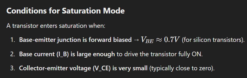
Saturation Region
In the Saturation Region, 𝑉𝐶𝐸 is small, so there is almost no voltage drop across the transistor, allowing maximum current to flow—just like a closed switch. The transistor allows maximum current flow from the collector to the emitter. The collector current (IC) is at its maximum possible value, determined by the circuit components. The collector-emitter voltage (VCE) drops to a small value (usually around 0.1V to 0.3V for silicon BJTs). In saturation, both the base-emitter and base-collector junctions are forward-biased, meaning there is no strong electric field opposing current flow. This allows free movement of charge carriers, making the transistor act like a low-resistance wire. Saturation mode is mainly used when a transistor functions as a switch in digital circuits. If the transistor is in saturation, the collector is almost at the same potential as the emitter (a very small voltage difference). The transistor can’t effectively control current using the base anymore.
Applications:
Switching Applications:
The saturation region is used when a transistor operates as a switch in the “ON” state.
Example: Turning on a motor, LED, or relay using a microcontroller.
Active Region
The active region occurs when the emitter-base junction (EBJ) is forward-biased, and the base-collector junction (BCJ) is reverse-biased. When the base current is greater than zero but does not exceed a certain threshold (e.g., a specific microampere value), the transistor operates in the active region. For a silicon transistor, 𝑉𝐵𝐸 is typically around 0.7V. For a germanium transistor, 𝑉𝐵𝐸 is lower, around 0.3V. If 𝑉𝐶𝐸 drops too low (below ~0.2V), the transistor enters saturation, and it no longer operates as an amplifier. If the transistor is in the active region, the collector voltage (𝑉𝐶) is significantly higher than the emitter voltage (𝑉𝐸), but lower than the supply voltage (𝑉𝐶𝐶).
The collector-emitter voltage (V_CE) varies between its maximum and minimum values. This allows the transistor to amplify signals. The active region is also known as the linear region because the collector current changes linearly with the base current. In this state, the transistor performs as an amplifier, operating as intended.
Applications:
Amplification:
Used in audio, RF, and signal processing circuits.
The transistor operates in the active region when it amplifies a signal.
Analog Circuit Design: Gain control, feedback circuits, etc.
Understanding Active Region
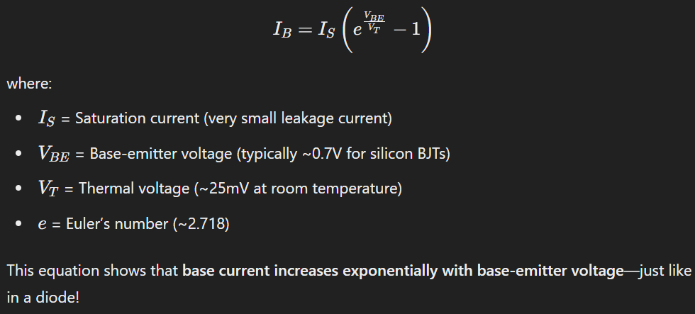
Base-Emitter Junction (V_BE) is Forward Biased (~0.7V for Silicon BJTs). This voltage remains approximately constant as long as the transistor stays in the active region. Small changes in 𝑉𝐵𝐸 result in exponential changes in base current (𝐼𝐵) due to the diode equation.
The base current (𝐼𝐵) controls the much larger collector current (𝐼𝐶).
Ideally, 𝐼𝐶 should only depend on 𝐼𝐵, but in reality, a small dependency exists on 𝑉𝐶𝐸. This effect is called the Early Effect (or base-width modulation). As 𝑉𝐶𝐸 increases, the depletion region at the collector-base junction widens, reducing the effective base width and slightly increasing 𝐼𝐶. This is because a narrower base allows for more efficient charge carrier transport from the emitter to the collector, reducing recombination of charge carriers in the base. As a result, more electrons or holes (depending on the type of transistor) reach the collector, increasing the collector current (IC).
This is why in the output characteristic curve (𝐼𝐶 vs 𝑉𝐶𝐸), the lines are not perfectly horizontal but have a slight upward slope.
Additional Software Tip (Reference Operator)
The & symbol in C++ can mean different things depending on its context. Let’s break down its meanings:
1. As a Reference Operator
Same Memory Location: The reference shares the exact same memory location as the original variable.
Two Names, One Variable: The original variable and the reference are just two different names for the same piece of data.
Synchronized Changes: Any change made through the reference directly affects the original variable (and vice versa).
Once initialized, a reference cannot be reassigned to refer to another variable. References need to be initialized when declared. Unlike pointers, references cannot be null. Passing by reference improves performance for large data structures.
1
2
3
4
5
unsigned long original = 42;
unsigned long& ref = original;  // ref is now a reference to original

ref = 100;  // Changing ref also changes original
Serial.println(original);  // Output: 100
Analogy
Think of a reference as a nickname:
If value is your real name and ref is your nickname, both refer to you.
Whether someone calls you by your real name or nickname, it’s still you who responds!
2. As an Address-of Operator
When & is used in front of a variable name (outside a declaration), it returns the memory address of that variable.
1
2
unsigned long value = 42;
unsigned long* ptr = &value;  // ptr stores the address of value
&value means “give me the address of value”.
This is commonly used with pointers to store addresses.
You can dereference the pointer using *ptr to access or modify the original value.
Benefits of using Reference Operator
Preferred for Readable Code
You can create a reference to simplify access to IR.decodedIRData.decodedRawData:
1
 unsigned long& rawData = IR.decodedIRData.decodedRawData;
Explanation
unsigned long& rawData creates a reference to IR.decodedIRData.decodedRawData.
You can now use rawData as a shorthand for IR.decodedIRData.decodedRawData.
Besides the Reference Operator, macros can also be used to replace variables or simplify access to values and code segments.
1
#define RAW_DATA IR.decodedIRData.decodedRawData
Replaces all instances of RAW_DATA with IR.decodedIRData.decodedRawData during compilation.
Caution
Macros don’t respect scope, so they can sometimes lead to unexpected behavior. Use references if possible for cleaner, safer code.